This example shows technique for calibrating sensor input and shows the sensor outputs by controlling LEDs and SSD, also shows how to monitor the state of a switch.
Hardware Required
8 LEDS
2 push button switches
2 sliding switches
4-SSD with MAX7221/7219
LM35
Speaker
Circuit
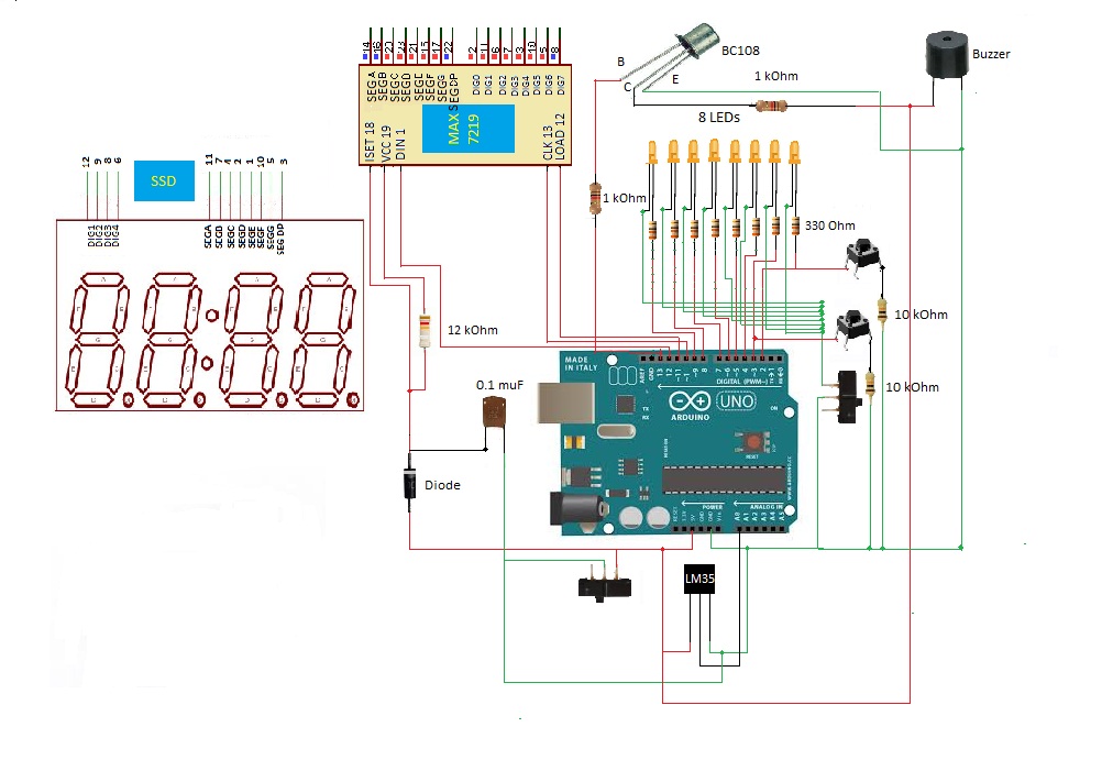
GPIO Arduino Shield complete circuit
In this circuit according to the above diagram 8 LEDs were connected to the Arduino digital pins 2 to 9. Pin 2 is the LSB and pin 9 is the MSB. 2 push buttons were connected to the pin 2 and pin 3. 2 sliding switches use to select either LED or SSD. SSD was connected to the Arduino using the MAX7219 driver.LM35 temperature sensor is a three pin component and its Vcc pin was connected to the 5 V pin of Arduino uno board, its ground pin to one of the ground pin of Arduino board and the output was connected to the one of the analog input pin of Arduino board. In this project buzzer was use as the speaker and it was connected to the Arduino through the BC108 NPN transistor.
Process
After opening the arduino-1.0.4-windows, upload the below given code to the Arduino. In this time nothing display in the arduino shield. After that open the serial monitor and there will be printed line “choose an option :1.C 2.F” Then have to type ‘1’ for temperature in Celsius and ‘2’ for temperature in Fahrenheit. After entering 1 or 2 there will be display current temperature value in serial monitor like this.“Temperature is: ‘corresponding temperature value’” .And also displays that value in the seven segment display. If temperature value belongs to the ranging that define to the LED, corresponding LED also light up. If any other value was entered other than 1 or 2 there will be another printed line as “Error” in the serial monitor. Here temperature not varies according to the variation in the environment. It holds temperature value until pass the serial value. It displays the temperature value at the moment that pass the serial value.
Here can control the output display methods. That is can get output only from ssd, LED or both. If output want to display in SSD just have to choose SSD using sliding switch and to display using LEDs have to select LEDs also using the other sliding switch. When the temperature gradually increases, it’s supposed ring an alarm due to the buzzer. But in this Arduino shield it wasn’t work due some problem of Arduino shield designing.
Schematic
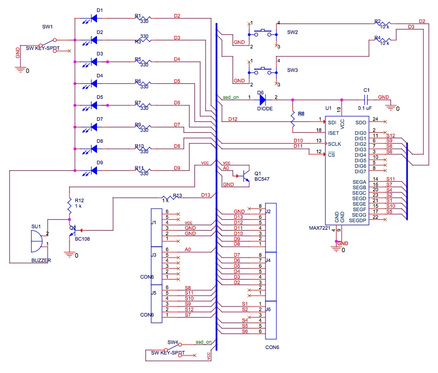
Schematic for GPIO Arduino Shield
Code
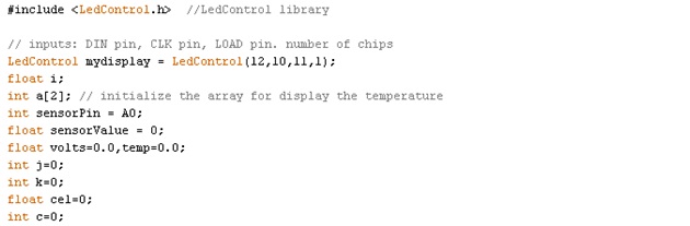
At the beginning of the code there is LedControl library. This is an important library, because without this library SSD won’t work.
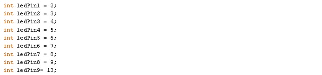
Below codes for initialize for digital pin 2 to 9 and digital pin 13.
According the second value of third line of the below code brightness of the SSD will be controlled. This will vary to 1 to 15. But higher values may be damage to the SSD or Max7219. So it is important to use low value than 8, to protect the circuit.

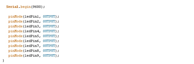
Below codes was used to begin serial communication at 9600 bits of data per second. And “pinMode” is used to set LEDs as output.
Using below codes temperature can be display as Celsius or Fahrenheit. After display “choose an option :1.C 2.F “ in the serial monitor, just have to type ‘1’ or ‘2’. If 1 was entered then current temperature of environment will be display in Celsius and if 2 were entered then the current temperature of environment will be display in Fahrenheit. Unless it will display as “Error” in the serial monitor.
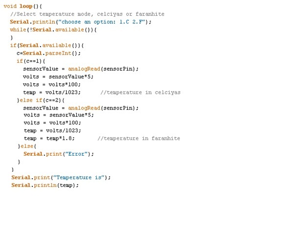
“Serial.print” is normally use to display things in the serial monitor.
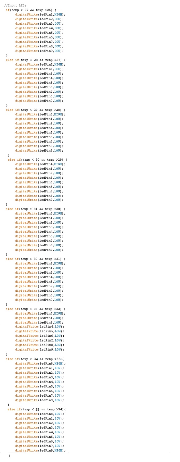
Below code is used to assign each LED for different temperatures. LEDs will be on gradually LSB to MSB according to the increase of temperature.
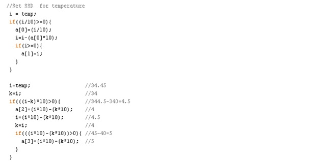
Given below is the method that uses to display the temperature value with floating points. Here after calculation temp value is initiated as ‘i’. Just think we want to display 34.45 as ‘i’. First ‘i’ value dived by 10(3.445) and if it greater than 0, it assign to the a[0]. As array defined as integer, int a[0] display 3.Then again ‘i’ defined as ‘i-a[0]*10’. So the next ‘i’ value equal to 4.45(34.45-3*10=4.45). Then it new ‘I’ value assign to the a[1].As a[1] also integer array a[1]=4.
Then have to display the values after the floating points. Here another variable define as ‘k’ and ‘k’ is a integer variable of ‘i’. So k=34. Then (i-k)*10 is equal to 4.5. Then it assign to the a[2]. As array a[] is defined to an integer a[2]=4.
Then again ‘i’ defined as ‘(i-k)*10’. So the new ‘i’ value is 4.5. Then it assign to ‘k’. As ‘k’ is an integer of ‘i’, k=4. If (i-k)*10(that is value 5) greater than 0, it assign to the a[3]. As value 5 is an integer it can directly assign as a[3].
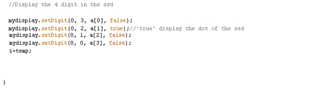
According to the below codes “mydisplay.setDigit(0 ,3, a[0], false)”, the first digit is for MAX7219 chip, normally it is ‘0’, second digit is for position of the digits of the SSD, third digit is the value of digit of SSD and the forth digit is for the dot of the SSD, when it is ‘true’ in line 2 of below code it will appear as floating point.
Conclusion
SSD will not display values when there is no LedControl library. That because Arduino library haven’t a library corresponding to the SSD display. Therefore corresponding library was downloaded and copied to the Arduino library section.
As some power failure, Max7219 not work properly. Then SSD always display all part in that. Therefore programe was not lode to the SSD. Always display all part of the SSD. Have to change the MAX7219. Then it works according to the code.
It displays numbers, characters properly. But when add iteration to the code, it not display properly. That is because it display very fast and cannot recognize to the eyes. But it works. It is the normal behavior of the SSD display. To overcome this problem, have to initiate the variable not only on the beginning of the code but also bottom of the code too.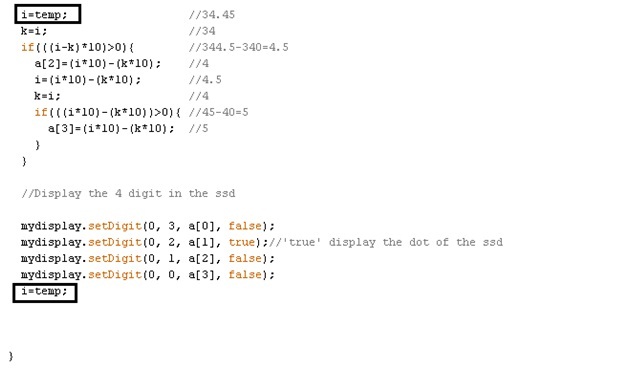
Normally LedControl library display as follows.
LedControl(DIN pin, CLK pin, LOAD pin. number of chips)
LedControl(12,11,10,1)
But because of some mistake in schematic CLK pin and LOAD pin interchange. So until find this error ssd not display anything that upload to the arduino board. So have to change the code as follows.
LedControl(12,10,11,1)
When all work properly, couldn’t display the last digit of the SSD. Until the end, couldn’t find the error corresponding to that.
Some LEDs were burned due to temperature of the soldering iron.
When the brightness of the SSD increase in more values, it gain more current and it will be cause to damage the Arduino board. Therefore the value of brightness keeps in value 3.