
If you’re a good Arduino programmer, you may know how to program an Arduino board with it’s libraries. In Arduinos also, there are Atmel MCUs. You’re doing is programming those MCUs using libraries that has provided by Arduino IDE. It’s something like programming with Java or C#. Just because it’s not difficult to programming like with C, everyone is using Java, C#. But if you need to understand concepts of real programming, you have to go with C, Assembly languages all the time. So in here also I’m going to explain concepts of programming a MCU with AVR libraries in C language.
You may need following components to follow this article.
- Arduino UNO/ Arduino MEGA board
- 8 LEDs
- 470 ohm Resistor
- Breadboard
- Jumper Cables
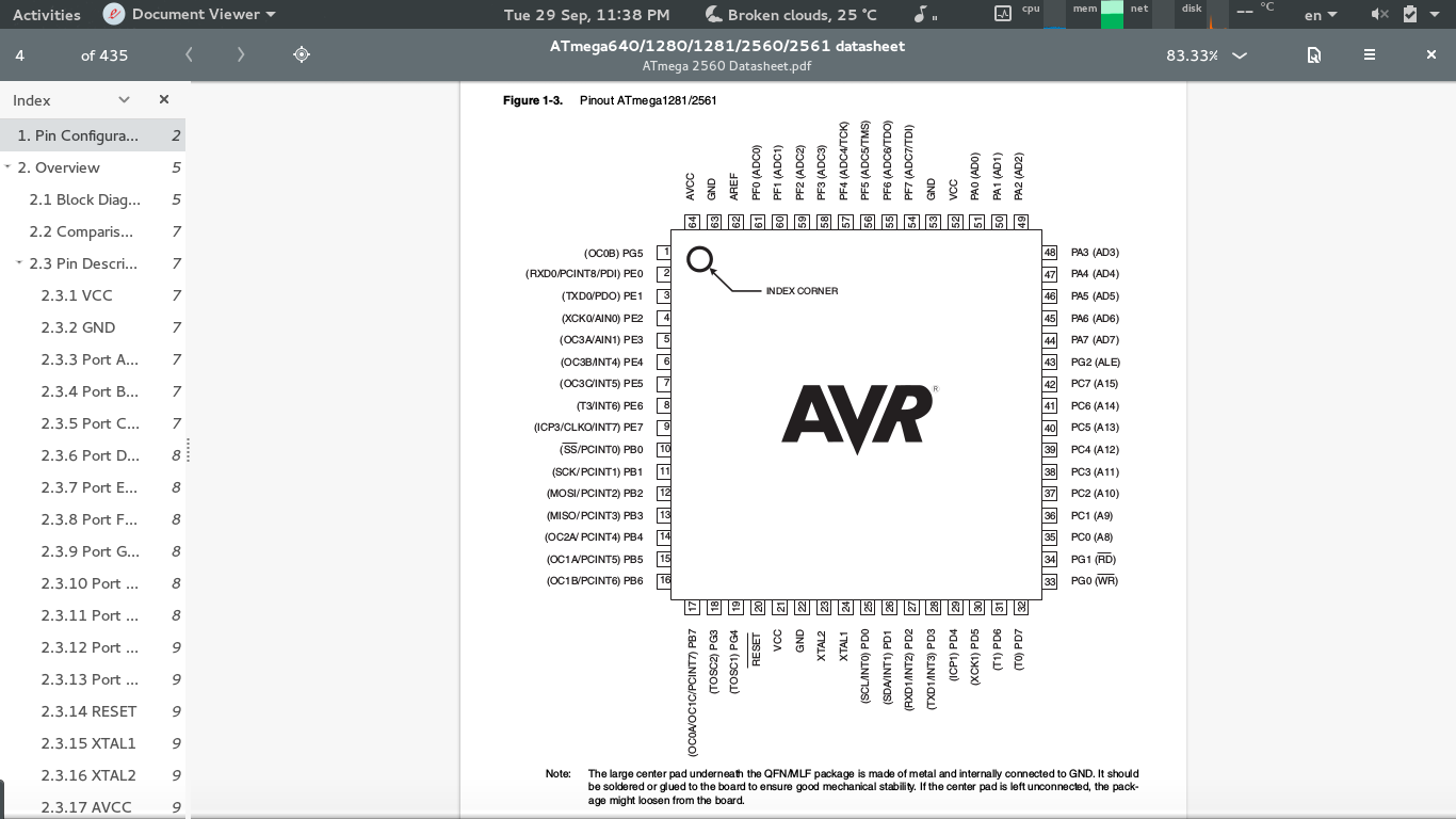
In Arduino MEGA there’s a Atmega2560 MCU and in UNO there’s a Atmega328 MCU. First just take a look at the datasheet of those MCUs. You could see that there’re so many ports in these MCUs. These ports could be used to do I/O operations with two states, 0 or 1 that is 0V or 5V.
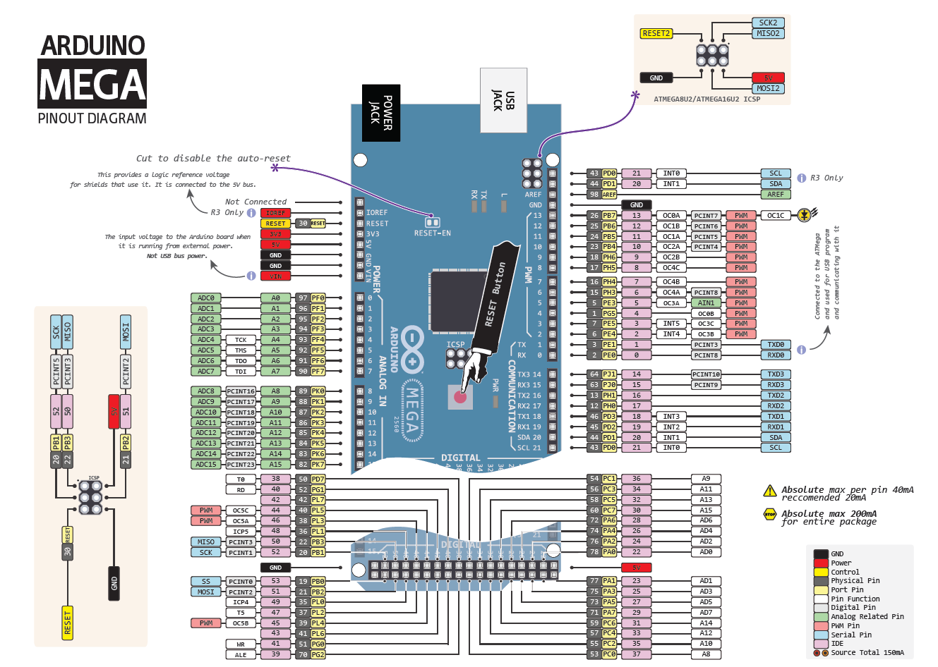
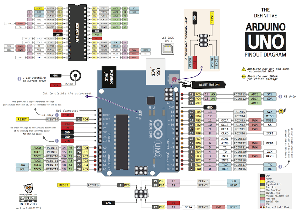
You may need following scetches so you may know to where those ports are connected in an Arduino MEGA and UNO boards.
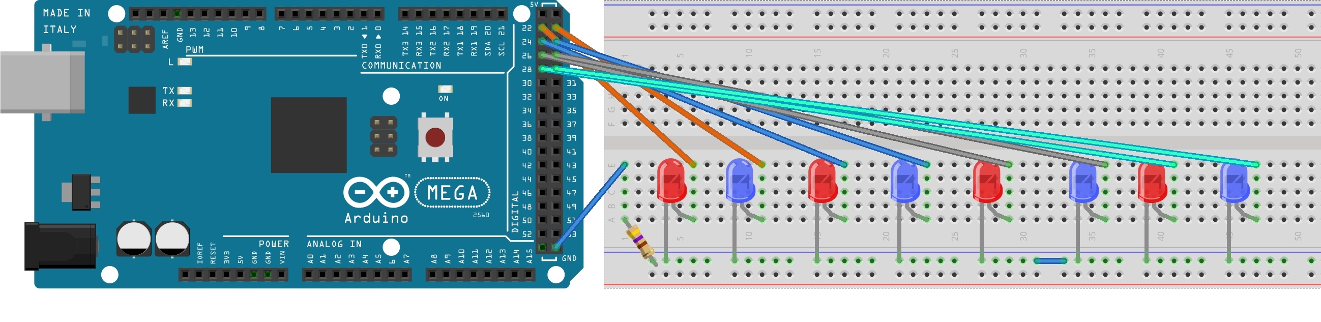
Now connect two LEDs to PA0 and PA1 pins and to ground through a resistor like follows.
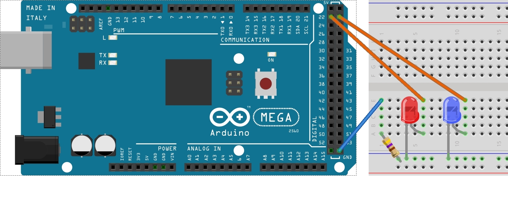
Breadboard Diagram 01
In Atmel MCUs, a port is a register which contains 8bits (sometimes it could be 6bits). Each digit of the 8bit is connected with a pin to do I/O operation with outside world.
| PA7 | PA6 | PA5 | PA4 | PA3 | PA2 | PA1 | PA0 |
| PB7 | PB6 | PB5 | PB4 | PB3 | PB2 | PB1 | PB0 |
Since a port could handle both I/O operations, we need to configure each digit of the port to an input or to an output. For that there’s a 8bit Data Direction Register (DDR) for each port. In DDR if a digit is 0, that means we have configured the corresponding port pin to an input. If a digit is 1 in the DDR, that means we have configured port pin to an output.
| PA7 | PA6 | PA5 | PA4 | PA3 | PA2 | PA1 | PA0 | |
| DDRA | 0 | 0 | 0 | 0 | 0 | 0 | 1 | 1 |
| PORTA | I | I | I | I | I | I | O | O |
In the above table, PA0 and PA1 pins are outputs because DDRA is configured to 1 for those pins. So now we could set PA0 and PA1 to 1 or 0 so it will give an output of 5V or 0V.
| PA7 | PA6 | PA5 | PA4 | PA3 | PA2 | 0 | 1 |
This will give 5V output from PA0 pin and 0V output from PA1 pin. So we could use this to light a LED bulb. In our sketch, we have connected two LEDs to PA0 and PA1. Now let’s do the coding part.
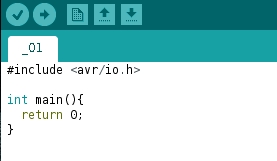
First we need to do is import avr/io.h libarary to the code. All registers of MCU is defined in this library. And create the main method.
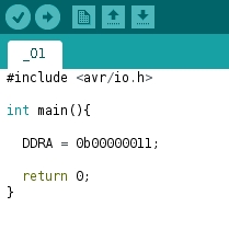
Now you need to configure DDRA register to give an output from PA0 and PA1. So you need to do is make PA0 and PA1 to 1s and others to 0. So the number will be 00000011 in binary. This value is equivalent to 3 in decimal and 0x03 in hexadecimal. You could set the DDRA value with any of these formats like follows.
DDRA = 0b00000011; // This is binary

DDRA = 3; // This is decimal

DDRA = 0x03; // This is hexadecimal
Now we have to do is give an ouput of 5V or 0V to the pins PA0 and PA1. For that you could change PORTA value to 00000011 using binary, decimal or hexadecimal values.
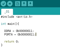
Now upload this code to your arduino so you’ll see the result.
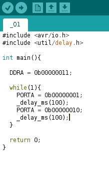
Now let’s do some change to this code with an infinite loop and delay to flash one LED at a time.
Infinite loop could be code as follows and you need to import util/delay.h to use delay options.
while(1){

}
If you need to use all 8 pins you could use following way.
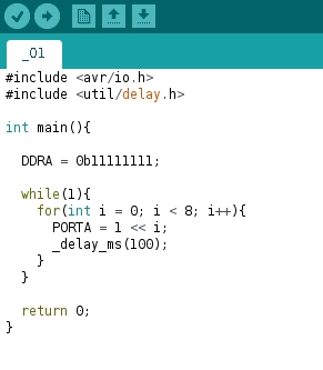
In here, 1 << 5 is equals to 10000. This is usual left shift operator in C.
If you have any suggestions to improve this article or if you have any question, please comment them here or send us an email to fosmedia@fos.cmb.ac.lk
Image Sources:
http://i.stack.imgur.com/EsQpm.png, http://www.bitsandparts.eu/documentation/299/ARDUINO.Mega.Pinout.Diagram.png