With the transition of the computer from the 2nd to the 3rd generation, the introduction of transistor-based circuitry was applied very meticulously and consistently in the design of the computer. This analog device served as one of the foundation points in the development of digital circuits, those which we cannot do without now in the modern world. The transistor is extremely important in electronics as it is a voltage-controlled switch. Unlike physical push switches, the transistor does not require physical manipulation for performing this task. This means that the transistor is, in essence, a self-functioning switch based on potential differences.
The Fundamental Switch
This switching process can be considered to be analogous to whether a current is allowed to pass or not. Consider a certain lower threshold of voltage as VLow where if the voltage supplied to the transistor circuit (VSup) is less than or equal to VLow, it is at the OFF position of the switch. Similarly consider an upper threshold of voltage as VHigh where if the supplied voltage is greater than or equal to VLow, then the transistor is at the ON position of the switch. We can illustrate this as follows.
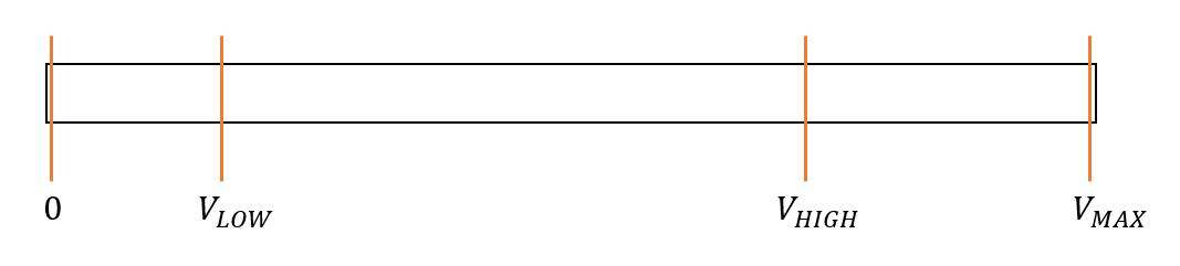
We can observe that there are three states to the switch, an ON position, an OFF position, and an indeterminate state where VSup ∈ (VLow, VHigh). By ignoring this indeterminate state we can consider the states ON and OFF only. That is whether the current is able to pass or not. We can now make a digital analogy to this by assigning the ON state of the transistor switch as 1 and the OFF position as 0. Thus forming a digitized language of the states 1 and 0, which we refer to as the “Boolean” number system. The algebraic operations based on this language is known as “Boolean algebra”.
Mathematical Logic
These algebraic operations are interspersed with mathematical logic. Mathematical logic can be quantified by statements that would give either a true (T) result or a false (F) result.
First consider logical negation, or what is known as the NOT property of logic. Here it simply indicates that for a statement A, the statement NOT A is the negation of A. That is, if statement A is true then statement NOT A is false and vice versa. We can depict it as below.
| Result of A | Result of NOT A |
| F | T |
| T | F |
Next consider logic addition, or what is known as the OR property of logic. Let A and B be two statements. We define the OR property to have a result of true when at least one of the above statements is true.
| Result of A | Result of B | Result of A OR B |
| F | F | F |
| F | T | T |
| T | F | T |
| T | T | T |
Now consider logic composition, or what is known as the AND property of logic. Let A and B be two statements. We define the AND property to be such that the result is true when both of the above statements are true.
| Result of A | Result of B | Result of A AND B |
| F | F | F |
| F | T | F |
| T | F | F |
| T | T | T |
Starting from these basic logical properties we can continue to build more complex logical properties. But before this concept is developed further, let’s consider the formation of these mathematical logic statements with electronic components.
The Analog Logic Construction
As mentioned earlier, the progression of science in semiconductor physics gave birth to diodes, transistors, and advanced forms of transistors such as Field Effect Transistors (FET) and Metal Oxide Semiconductor Field Effect Transistors (MOSFET). These are the building blocks of the digital components that handle mathematical logic operations, named “logic gates”.
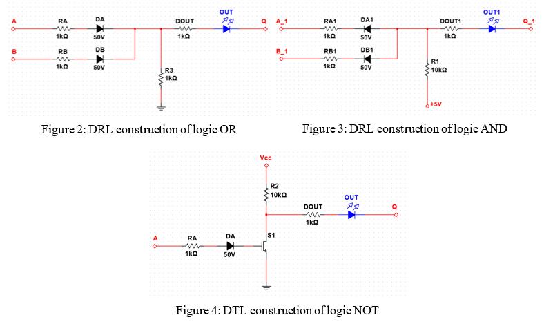
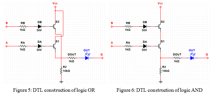
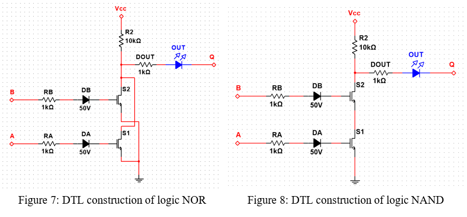
Among the many techniques used to make logic gates, the most common are the Diode-Resistor-Logic (DRL), Diode-Transistor-Logic (DTL), Transistor-Transistor- Logic (TTL) and Metal-Oxide-Semiconductor-Logic (MOS-Logic) methods. These methods differ from each other based on the electrical components used in them. Below are a few such constructions of the NOT, OR, and AND logic gates.
A Further Step Into Logic
We can now move on to examine the further development of the three basic logic properties discussed above. The first would be the combination of the NOT and OR logic properties, the NOR property. In other words, this is the negation of the OR property. Thus we can define the NOR logic as that which is true only when both logic statements are false.
| Result of A | Result of B | Result of A NOR B |
| F | F | T |
| F | T | F |
| T | F | F |
| T | T | F |
The same arrangement can be done to the logic property AND, creating the NAND logic property. This implies that the NAND logic property is true if at least one of the input logic statements is false.
| Result of A | Result of B | Result of A NAND B |
| F | F | T |
| F | T | T |
| T | F | T |
| T | T | F |
A property with a more complex form of logic can be constructed as the XOR or exclusive OR logic. This is defined as a logic property with a true result if the two logic statements have differing results. The negation of this property, the XNOR or exclusive NOR logic is defined to be having a true result if the two logic statements have the same results. Below are the representations of these two properties.
| Result of A | Result of B | Result of A XOR B | Result of A XNOR B |
| F | F | F | T |
| F | T | T | F |
| T | F | T | F |
| T | T | F | T |
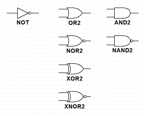
These logic properties that are constructed using electronic components are represented in digital circuits as follows.
From Pieces of Logic to Operations
With this, we can finally consider the market form of logic gates, which are used in the actual physical construction of the circuits. A variety of ICs is present in the modern-day that contains a fixed number of a specific type of logic gate within them. The number of inputs that can be provided to each gate is also taken into consideration here.

Using these fundamental concepts of logic, and the fact that the market contains only a limited number of logic gates per IC; we can come to the requirement of simplifying logic expressions. This task is carried out through the use of Boolean Algebra.
Image Courtesies
01.Featured Image: https://bit.ly/3eJ1iNH