When you’re using external crystal oscillator for an AVR based Atmel MCU, you need to change the High Fuse Byte and the Low Fuse Byte in order to disable internal oscillator of the MCU and to enable the use of external oscillator. Not only that, these fuse bits could be used in other options too. These things you could find out by reading the specific datasheet of the MCU.
So what happens if you program these fuse bits in a wrong way is, you may be unable to program the MCU again and therefore the entire MCU will be useless. There’s a way to correct the fuse bits using high voltage programming. In high voltage programming method, 12V input will be given to the Reset pin of the MCU.
When you’re creating the circuit, make sure that you have a common ground and NOT a common +5V (even if you regulate the 12V to 5V for some reason) between arduino and the rest of your circuit. If you regulate the 12V to 5V and make it common with arduino’s 5V, it may damage your arduino and the computer.
Here we’re using Atmega328P MCU as the MCU which needs to be rescued and a Arduino DUE. This code should be working fine with Arduino MEGA version. Please read the datasheet of the MCU before continuing.
Required Components
- Arduino DUE (or MEGA)
- 1kΩ resistors (20 of them)
- LED
- Jumper wires
- Atmega 328p MCU
- 12V DC power supply
- BC338 or 2N3904 Transistor (or any NPN transistor)
- Push Button
- Breadboard
Circuit Diagram

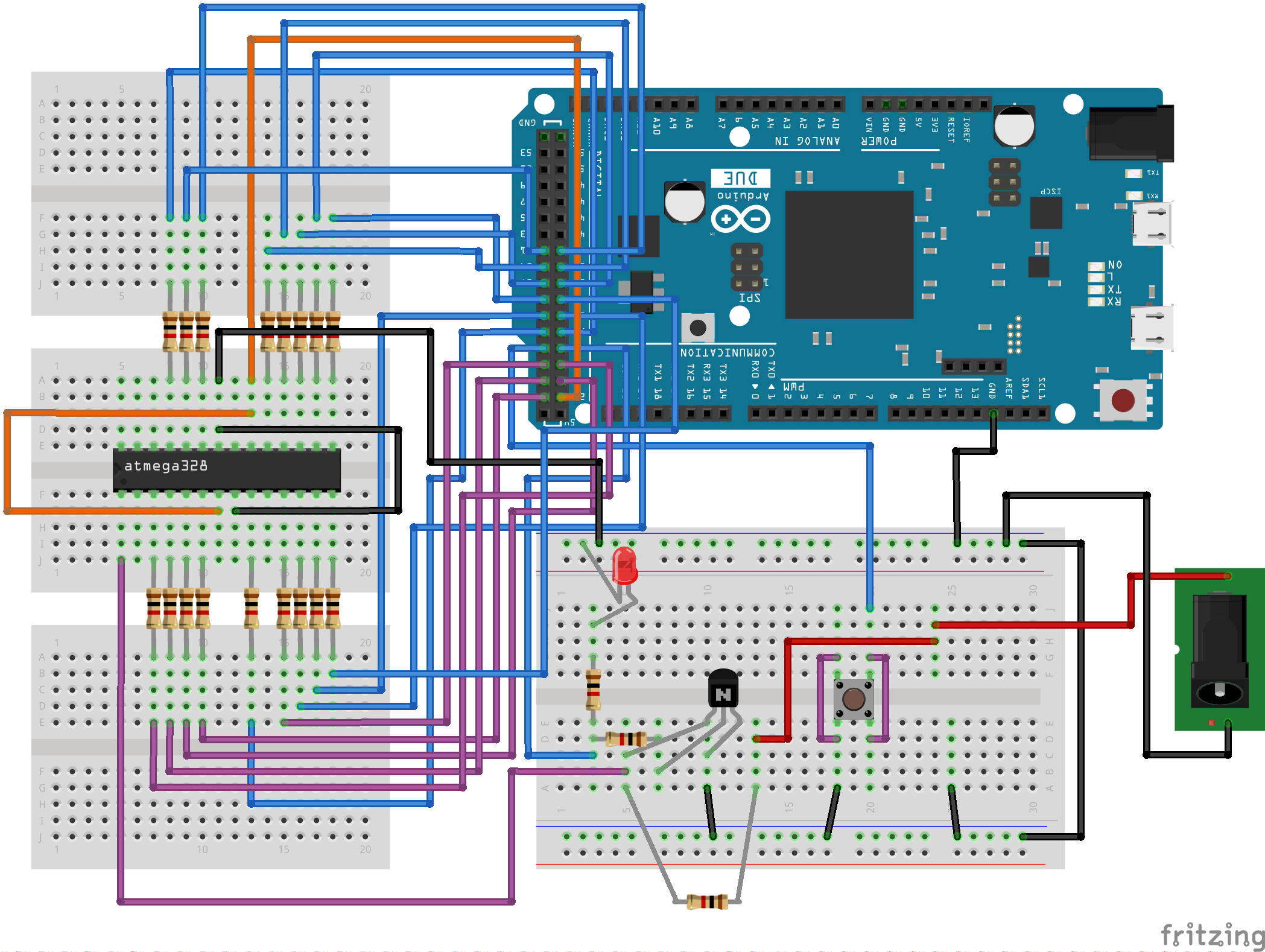
Each input pin between Arduino and Atmega328p MCU is protected with a 1kΩ resistor. If you don’t need protection, these resistors could be removed. Please make sure all components are connected correctly before you turn ON power.
Code
Before uploading the code into the Arduino, find the default High Fuse Byte and the Low Fuse Byte for the MCU by reading the datasheet and replace the value of HFUSE and LFUSE with them.
#define HFUSE 0xD9
#define LFUSE 0x62

void setup()
{
 //Power
 pinMode(22, OUTPUT); //VCC & AVCC
 digitalWrite(22, LOW);

 pinMode(23, OUTPUT); //PD4
 digitalWrite(23, LOW);
 pinMode(24, OUTPUT); //PD3
 digitalWrite(24, LOW);
 pinMode(25, OUTPUT); //PD2
 digitalWrite(25, LOW);
 pinMode(26, INPUT);  //PD1
 digitalWrite(26, LOW);
 pinMode(27, OUTPUT); //PD5
 digitalWrite(27, LOW);

 pinMode(28, OUTPUT); //RESET
 digitalWrite(28, HIGH);
 pinMode(29, INPUT);  //BUTTON)
 digitalWrite(29, HIGH);
 pinMode(30, OUTPUT); //PC2
 digitalWrite(30, LOW);
 pinMode(31, OUTPUT); //PB6
 digitalWrite(31, LOW);
 pinMode(32, OUTPUT); //PD6
 digitalWrite(23, LOW);
 pinMode(33, OUTPUT); //PD7
 digitalWrite(33, LOW);

 pinMode(34, OUTPUT); //PB0
 digitalWrite(34, LOW);
 pinMode(35, OUTPUT); //PB1
 digitalWrite(35, LOW);
 pinMode(36, OUTPUT); //PB2
 digitalWrite(36, LOW);
 pinMode(37, OUTPUT); //PB3
 digitalWrite(37, LOW);
 pinMode(38, OUTPUT); //PB4
 digitalWrite(38, LOW);
 pinMode(39, OUTPUT); //PB5
 digitalWrite(39, LOW);
 pinMode(40, OUTPUT); //PC0
 digitalWrite(40, LOW);
 pinMode(41, OUTPUT); //PC1
 digitalWrite(41, LOW);
}

void progHFUSE(){
 //Send Command
 digitalWrite(32, HIGH);
 digitalWrite(27, LOW);
 digitalWrite(23, LOW);

 for(int i = 34; i <= 41; i++){
  if(i == 40){
   digitalWrite(i, HIGH);
  }else{
   digitalWrite(i, LOW);
  }
 }

 digitalWrite(31, HIGH);
 delay(1);
 digitalWrite(31, LOW);
 delay(1);

 //Write Fuse
 digitalWrite(32, LOW);
 digitalWrite(27, HIGH);
 delay(1);

 for(int i = 34; i <= 41; i++){
  if(HFUSE & (1 << (i - 34))){
   digitalWrite(i, HIGH);
  }else{
   digitalWrite(i, LOW);
  }
 }

 digitalWrite(31, HIGH);
 delay(1);
 digitalWrite(31, LOW);

 digitalWrite(23, HIGH);
 digitalWrite(24, LOW);
 delay(1);
 digitalWrite(24, HIGH);
 delay(100);
}

void progLFUSE(){
 //Send Command
 digitalWrite(32, HIGH);
 digitalWrite(27, LOW);
 digitalWrite(23, LOW);

 for(int i = 34; i <= 41; i++){
  if(i == 40){
   digitalWrite(i, HIGH);
  }else{
   digitalWrite(i, LOW);
  }
 }

 digitalWrite(31, HIGH);
 delay(1);
 digitalWrite(31, LOW);
 delay(1);

 //Write Fuse
 digitalWrite(32, LOW);
 digitalWrite(27, HIGH);
 delay(1);

 for(int i = 34; i <= 41; i++){
  if(LFUSE & (1 << (i - 34))){
   digitalWrite(i, HIGH);
  }else{
   digitalWrite(i, LOW);
  }
 }

 digitalWrite(31, HIGH);
 delay(1);
 digitalWrite(31, LOW);

 digitalWrite(23, LOW);

 digitalWrite(24, LOW);
 delay(1);
 digitalWrite(24, HIGH);
 delay(100);
}

void loop(){

 while (digitalRead(29)) {}

 digitalWrite(50, HIGH);
 digitalWrite(48, LOW);

 // Initialize pins to enter programming mode
 digitalWrite(33, LOW);
 digitalWrite(32, LOW);
 digitalWrite(30, LOW);
 digitalWrite(27, LOW);
 digitalWrite(23, LOW);

 // Enter programming mode
 digitalWrite(22, HIGH);
 digitalWrite(24, HIGH);
 digitalWrite(25, HIGH);
 delay(1);
 digitalWrite(28, LOW);
 delay(1);

 // Program HFUSE
 progHFUSE();

 // Program LFUSE
 progLFUSE();

delay(1000);

 // Exit programming mode
 digitalWrite(28, HIGH);

 // Turn off outputs
 for(int i = 34; i <= 41; i++){
  digitalWrite(i, LOW);
 }

 digitalWrite(22, LOW);
 digitalWrite(24, LOW);
 digitalWrite(25, LOW);
 digitalWrite(27, LOW);
 digitalWrite(23, LOW);

 digitalWrite(33, LOW);
 digitalWrite(32, LOW);
 digitalWrite(30, LOW);
}
Now upload the code and give power to the circuit. If the circuit is correct, the LED will turn ON. Now press the push button so the LED will be turned off. Now wait for LED to turn back ON again. This might take a few seconds. Now the fuse should be corrected. Try uploading a program to the MCU to verify.
Please use these references if you need to learn more about rescuing fuse bits.
http://www.instructables.com/id/AVR-High-voltage-programming-Fuses-rescue/?ALLSTEPS
http://denki.world3.net/avr_rescue.html
If you have any questions or ideas to improve this article, please send them to our official e-mail address or comment below.