With the boom of transistors and diodes, the floodgates to the dam holding back technology were suddenly opened. This lead to what could be considered as the biggest leap in technology mankind witnessed. Soon, the revolution of electricity, or rather that of electronics gave way to the concept of embedding many circuits into one patch. In a world that was growing with digital and analog signals, now enters the Operational Amplifier, or the Op-Amp.
An analog electronic device capable of converting input voltage signals into amplified output signals of varying nature, this is one of the most useful fundamental devices in electronics.
Here the terminal V+ is termed the non-inverting terminal and V– the inverting terminal. Inputs are provided to the Op-Amp via these two terminals. The terminals Vs+ and Vs- are connected to a power supply. A VCC and VEE supply, or a constructed dual DC power supply can be used.
Image 01: Schematic of an Operational Amplifier
The output of the Op-Amp is obtained through the Vout terminal.
The Idealism in the Basics
A basic outline of an ideal Op-Amp is based on first considering the input impedance (Zin) built within it is infinitely large. Since by definition, the input impedance is Vin / Iin this implies that the current flowing in through the input terminals is negligible (ideally 0). Since no current flows through the terminals we can now write the input voltage as the difference between the two input terminal voltages.
Vin = (V+ – V–)
Now consider that the output impedance (Zout) is negligibly small, or in other words, 0. this implies that the current flowing out of the Op-Amp is infinitely large. Since the definition of impedance gives us that Zout = Vout / Iout = Rout we have the fact that the output resistance of the Op-Amp is 0. Thus no voltage is dropped from the input to the output.
The only effect that happens is the amplification of the voltage by a certain gain value (G). Thus we can write the output voltage of the Operational Amplifier as follows.
Vout = G * Vin = G * (V+ – V–)
The above implies that the output voltage is independent of any load which is connected to the output circuit of the Op-Amp. Since the output voltage is a function of the difference of two input voltages this is known as a difference amplifier.
The Application of the Amplification
From the above ideal conditions, a few “Golden” rules for an Operational Amplifier can be brought up.
#01: In an ideal Op-Amp, the Open-Loop Gain is infinitely large. #02:The input impedance between the two input terminals is infinitely large, thus no current flows within the Op-Amp.
What it implies of an Open-Loop Gain being infinitely large is that G = Vout / (V+ – V–) is infinitely large. This leads to the expression 0 = (V+ – V–).
Using this, two fundamental configurations of the Op-Amp can be introduced based on the way voltage signals are connected to the input terminals.
Amplifier of Inversion, or Not?
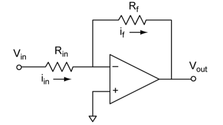
The first configuration, the “Inverting Amplifier”, is constructed by virtually grounding the non-inverting terminal (V+) and supplying an input voltage through an input resistor (Rin). Here, a feedback resistor (Rf) is connected to the output of the Op-Amp as shown below.
Image 02: Inverting Operational Amplifier
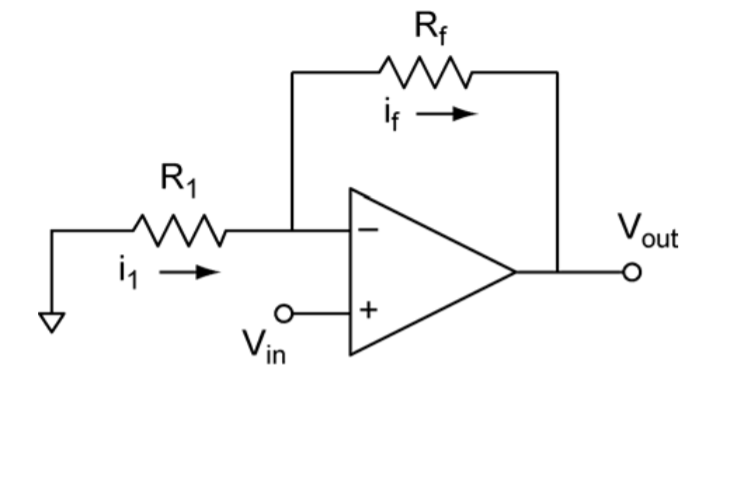
The next configuration, the “Non-Inverting Amplifier”, is constructed by doing the opposite as earlier, by virtually grounding the inverting terminal (V–) through an input resistor (Rin) and supplying an input voltage through the non-inverting terminal. Here too, a feedback resistor (Rf) is connected to the output of the Op-Amp as shown below.
Image 03: Non-Inverting Operational Amplifier
Summing it all up, with Amplification
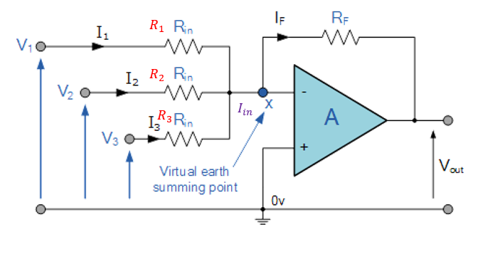
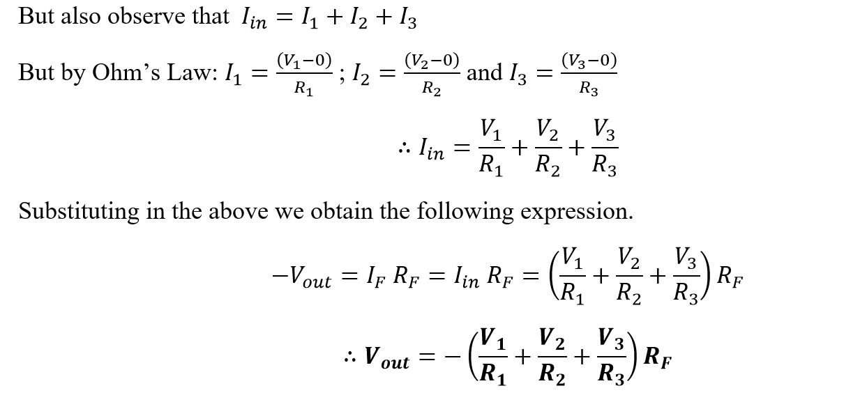
Using these two fundamental configurations, Operational Amplifiers can be used in many ways to perform mathematical functions. The mathematical logic of addition can be performed on digital electronic signals using the following setup now.
Image 04: Summing Amplifier
Thus we can see how Operational Amplifiers can be used to add input voltage signals together and present them as an inverted output. This, while seemingly simple, is the basis for the construction of an extremely important application of Op-Amps, the Digital-to Analog-Converter (DAC), and the Analog-to-Digital-Converter (ADC).
References:
01. Tooley, M. (2006). Electronic Circuits: Fundamentals and Applications. Burlington: Elsevier Ltd.
02. Nelkon, M. & Parker, P., 1995. Advanced Level Physics 7th Edition Reprint. Delhi, India by arrangement with Heinemann Publishers (Oxford) Ltd., U.K.: CBS Publishers and Distributors Pvt. Ltd.