“A few weeks ago, we the members of Team-H, debated opposing the fact that, “When we compare electrons and photons, electrons are the best sources to investigate molecular structures.” It was one of the 5 interesting and twisting chemistry topics that we got. Knowing that the proposition team will bring out the electron microscope, with the highest resolution achieved so far, it was clear that we had to bring up a broader scope of photon-based investigation techniques, rather than merely pointing out the disadvantages of the electron microscopes. Out of the many techniques, Surface Plasmon Resonance Microscopy was one interesting concept.”
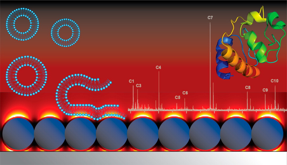
Surface Plasmon Resonance Microscopy is a powerful optical detection technique to study label-free biomolecular interactions in real-time within their native environments. The underlying theoretical basis behind it is the interaction between incident electromagnetic waves and the free electrons present in the metal.
In the instrumentation setup, the biomolecules such as proteins, antibodies, nucleic acids are allowed to retain on a metal surface. A polarized light ray (of a single wavelength) is then directed to the lower surface of the metal through a glass prism, and the reflected light ray is directed to a detector. Before discussing further on the application, it is vital to have some understanding of this underlying principle.
Evanescent Waves
Most of us know what total internal reflection is. It is a phenomenon where a light ray traveling from a denser medium to a rarer medium (in terms of refractive index) reflects at the interface (the margin of the two mediums). This occurs when the incident angle is greater than the critical angle for that respective medium. But is total internal reflection, really a “total” internal reflection?
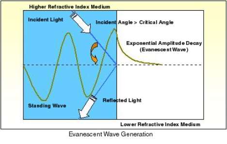
Even though the fully reflected light beam does not lose any energy across the interface, it leaks out an electrical field intensity called an Evanescent Field, into the rarer medium.
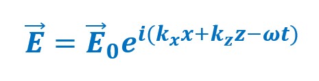
A plane light is an electromagnetic wave that has both the electric field and the magnetic field perpendicular to each other and the direction of propagation. The general equation for a plane light wave when represented in terms of the electric field is as follows.

Here “E” is the electric field vector of the transmitted wave and “E0“ is the constant electric field vector amplitude. The term “k” is the propagation vector, and “ω” represents the frequency of the light used. Since 3 propagation directions are possible, 3 “k” terms can be incorporated.
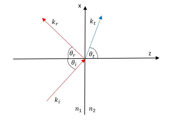
As in the diagram shown, even with total internal reflection occurring, there is no transmitted wave in the y-direction, which is directly perpendicular to the screen. The transmitted wave travels along the x-z plane, which reduces the previous equation to:
Nevertheless, the propagation of the wave in the z-direction becomes imaginary, where kz=αi. This further resolves the equation with the use of geometry and mathematics to:

The whole physical meaning of “kz ” being imaginary suggests that the wave decays in the z-direction. If the imaginary component lies in the direction of propagation, the wave undergoes damping. But in the case of evanescent waves, the wave propagates in the x-direction and damping occurs in the z-direction, suggesting that there is no loss of energy in the direction of propagation.
The Resonance Angle
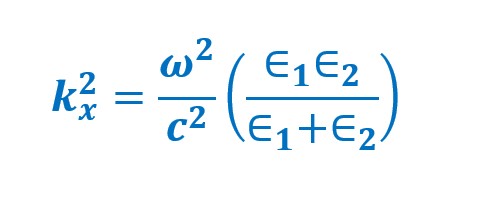
With the use of Maxwell’s equations, a dispersion relation along the x and z directions can be obtained where “ε1” and “ε2” are the dielectric constants of the two mediums and “c” being the speed of light.
At a specific incident angle called the resonance angle, a part of the energy of the incident light beam is absorbed by the electrons of the metal surface causing them to resonate. These electrons are known as surface plasmons and are extremely sensitive to changes in the nature of the contents on the metal surface. This causes a resulting intensity loss in the reflected light beam (via the light-evanescent field) which appears as a dark band that is related to a dip (trough) in the SPR reflection intensity graph.
The shape of the graph and the position of the SRP dip can be used to identify relevant information about the contents of the metal surface.
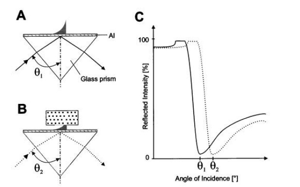
The figure above explains the principle clearly, where the resonance angle increases when a dielectric body (dotted-rectangle in image B) is brought into the region of the evanescent field (shown as a dark decay curve). Here the resonant excitation of the surface plasmons is shifted to larger angles. This phenomenon sweeps the entire area of the specimen of interest.
Kinetics in SPR
SPR can be used to observe the time-dependent binding interactions between molecules. Relating to the reflected light beam, an SPR signal can be measured over time to generate a plot called a Sensogram. In simple terms, when molecules bind to specific binding partners which are present on the metal surface, the SPR signal increases. When they dissociate or unbind, the SPR signal decreases.
Consider the above scenario where an analyte, containing molecules that can bind to specific sites on the metal surface is introduced. When considering the SPR response vs time plot, the rapid increase in SPR response suggests that the molecules just started binding to the specific sites, where a larger number is initially vacant.
With time, the gradient decreases, suggesting that the binding sites are occupied by incoming molecules. This decreases the binding rate and eventually reaches an equilibrium. Once the molecules unbind from the surface, the SPR response decreases with time as animated above.
By studying the variation of the decreased intensity of the photons detected, against the incident angle, the affinity, kinetics of even the nanometer scale binding events of viruses can be investigated. In this machinery, the cells that we need the molecular structures to be investigated are grown on the surface of the metal sensor chips, thus maintaining their native environment. This neglects the laborious time-consuming methods to extract biomolecules from cells.
With the relatively affordable price, ease of use, and increased sensitivity, SPRM has proved its worth by overcoming the sophistication barrier as a novel technique to investigate and quantify molecular interactions and structures.
Image Credits:
- Featured image: https://bit.ly/3AKtgR5
- Figure 1: https://bit.ly/3xOgD5x
- Figure 2: Author
- Figure 3: Snip from Biophysical Journal Volume 76 January 1999, Page 511.
- Video 1: https://bit.ly/3guJJkA
- Video 2: https://bit.ly/3mygZLW
- Video 3: https://bit.ly/389x4iJ
References:
- https://www.aacc.org/cln/articles/2019/may/the-role-of-surface-plasmon-resonance-in-clinical-laboratories
- https://www.photonics.ethz.ch/fileadmin/user_upload/Courses/NanoOptics/plasmonss.pdf
- Imaging of Cell/Substrate Contacts of Living Cells with Surface Plasmon Resonance Microscopy, K.-F. Giebel,* C. Bechinger,* S. Herminghaus,* M. Riedel,*P. Leiderer,* U. Weiland,# and M. Bastmeyer# *Faculty for Physics and #Faculty for Biology, University of Konstanz, D-78457 Konstanz, Germa
- Phase-Sensitive Surface Plasmon Resonance Sensors: Recent Progress and Future Prospects, Shijie Deng, Peng Wang * and Xinglong Yu, Published: 5 December 2017