In this tutorial, blinking led application implemented using built in libraries for STM32F3VC. Using libraries make things easy and no need to go to datasheet to implement every code. Every register location is defined with human readable values and it makes things easy.
First create a new project as mentioned in previous tutorials and add M4 CMSIS core, cmsis_boot, RCC, GPIO libraries from repository.
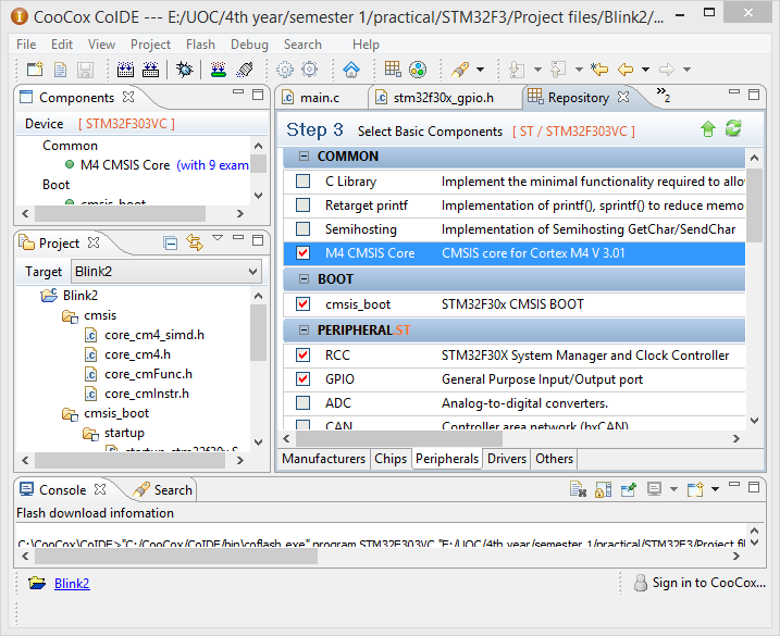
Blinking Project libraries
Then write following code
#include <stm32f30x.h>
#include <stm32f30x_rcc.h>
#include <stm32f30x_gpio.h>

int main(void)
{
	volatile unsigned int i=0;
	//Enable clock for GPIOE
	RCC_AHBPeriphClockCmd(RCC_AHBPeriph_GPIOE,ENABLE);

	//SET GPIO PIN 13 as output
	GPIO_InitTypeDef GPIO_InitStruct;
	GPIO_InitStruct.GPIO_Pin = GPIO_Pin_13;
	GPIO_InitStruct.GPIO_Mode = GPIO_Mode_OUT;
	GPIO_InitStruct.GPIO_Speed = GPIO_Speed_Level_3;
	GPIO_InitStruct.GPIO_OType = GPIO_OType_OD;
	GPIO_InitStruct.GPIO_PuPd = GPIO_PuPd_UP;

	// Initialization of GPIO PORTE PIN 13
	GPIO_Init(GPIOE,&GPIO_InitStruct);

    while(1)
    {
    	GPIO_SetBits(GPIOE,GPIO_Pin_13); //set pin 13 high
    	for ( i = 0; i < 1000000; ++i) ; //delay
    	GPIO_ResetBits(GPIOE,GPIO_Pin_13); //set pin 13 low
    	for ( i = 0; i < 1000000; ++i) ; //delay
    }
}
Understanding the code
First three lines of the code includes library files necessary for the project. stm32f30x_rcc.h file handles the reset and clock control and stm32f30x_gpio.h file handles General purpose input and output.
RCC_AHBPeriphClockCmd(RCC_AHBPeriph_GPIOE,ENABLE);
Above line enables clock for GPIOE. As you can see this line does not include any datasheet values directly because these user friendly values are pre-defined in library files. Therefore one can understand or at least guess what this means. If you look into these header files it contains a doctype comment which includes help for function. The CooCox IDE support this doc type comments and it shows it as a help for the function.
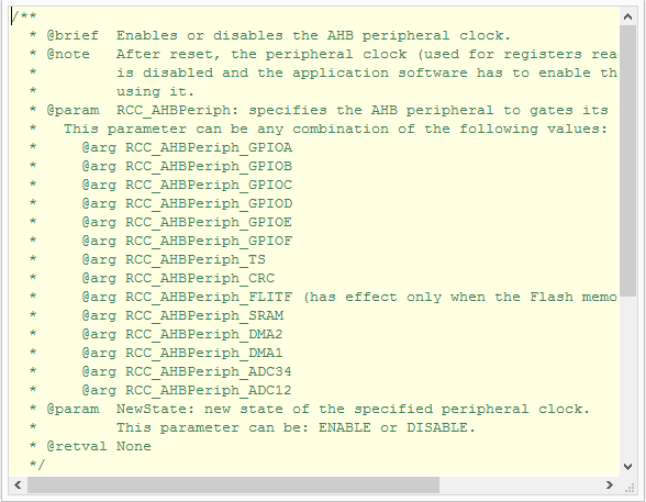
Library Doc type comment help
See the doc type comment help for above used function. It contains matching parameter for the function also. So no need of memorizing things and it make coding really easy.
Following code snippet shows how to set up GPIO functions using built in libraries.
        GPIO_InitTypeDef GPIO_InitStruct;
	GPIO_InitStruct.GPIO_Pin = GPIO_Pin_13;
	GPIO_InitStruct.GPIO_Mode = GPIO_Mode_OUT;
	GPIO_InitStruct.GPIO_Speed = GPIO_Speed_Level_3;
	GPIO_InitStruct.GPIO_OType = GPIO_OType_OD;
	GPIO_InitStruct.GPIO_PuPd = GPIO_PuPd_UP;

	// Initialization of GPIO PORTE PIN 13
	GPIO_Init(GPIOE,&GPIO_InitStruct);
It is really important to understand this coding style used in here. This is the way of initializing things in STM32 programming. First a suitable structure object must create. In this case GPIO_InitTypeDef structure was created as GPIO_InitStruct. Then its structure variable should fill using suitable values. Now the problems is how one can know suitable values. It’s pretty simple with an IDE like CooCox. When you can’t decide structure variable or values for that press CTRL + SPACE and IDE will display list of suggestions which you can use.
GPIO_Pin which is another structure variable, contains list of pins which we want to change. One or more pins can be set using OP operator.
Eg;
GPIO_InitStruct.GPIO_Pin = GPIO_Pin_12 | GPIO_Pin_13| GPIO_Pin_14;
GPIO_Mode sets the mode of pin we discussed in previous tutorials. One of four mode can be set at a time.
  GPIO_Mode_IN   = 0x00, /*!< GPIO Input Mode */
  GPIO_Mode_OUT  = 0x01, /*!< GPIO Output Mode */
  GPIO_Mode_AF   = 0x02, /*!< GPIO Alternate function Mode */
  GPIO_Mode_AN   = 0x03  /*!< GPIO Analog In/Out Mode      */
GPIO_Speed sets the speed for peripheral(following values are valid only for STM32F303VC only)
  GPIO_Speed_Level_1  = 0x01, /*!< Fast Speed     */
  GPIO_Speed_Level_2  = 0x02, /*!< Meduim Speed   */
  GPIO_Speed_Level_3  = 0x03  /*!< High Speed     */
GPIO_OType set out put type as Output push-pull or Output open-drain.
GPIO_OType_PP = 0x00,
GPIO_OType_OD = 0x01
GPIO_PuPd Configure Pull-Up, Pull-Down of pins
  GPIO_PuPd_NOPULL = 0x00,
  GPIO_PuPd_UP     = 0x01,
  GPIO_PuPd_DOWN   = 0x02
GPIO_Init Initializes the GPIOx peripheral according to the specified parameters in the GPIO_InitStruct.
Rest of the program is same as previous one and GPIO_SetBits(), GPIO_ResetBits() functions used to set value 1 and 0 for pins respectively.
Now compile the project as described in previous tutorial and flash into board. Next tutorial will be based on Interfacing buttons.
Watch the video below.