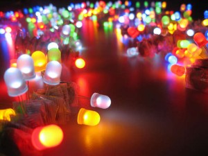
Most of the times the first lesson for microcontroller programming or embedded systems, is illumination of a LED or may be blinking LED using respective port pin. Most of the demonstrator boards starting from very simple ones to high end are having a LED or several with hardware which can make appropriate illumination. What makes the appropriate illumination of a LED….?
Unlike ICs like microcontrollers, DIYers are not encouraged to follow a data sheet for a LED. But according to my experience, I had in my research, LEDs are also care taken as well as ICs for a optimum illumination. There are lot of precautions to be adhere while handling and soldering a LED.
Check them in data sheet in following link;
http://www.roithner-laser.com/datasheets/led_div/infrared/led735-series.pdf
Other than that, I would like to discuss about proper hardware implementation for illumination of a LED via the theory behind that.
Illumination of a LED is basically depends on 3 things. They can stated as below,
- Peak wavelength
- Forward voltage
- Forward current
Wavelength
What you seen as LED’s color is scientifically a beam of visible light from a respective wavelength. Visible range of Electromagnetic spectrum ranges through 400 nm to 700 nm. According to the velocity equation, v = f.λ ; the frequency range of visible light can be calculated. It is approximately 430 THz to 750 THz. However, this light beam arises due to the recombination of electrons and holes near the junction of LED. Mind that, a conventional LED is a pn junction as a diode developed under opto electronics. The corresponding bandgap at the junction and its energy difference determines the wavelength which corresponds to the energy emission as photons.
Forward voltage
According to the equation, E = hν ; substituting ν as c/λ, can be modified as E = hc/λ.
Now the Potential Energy(E), can be converted to a voltage difference by dividing it by elementary charge. (JC-1 = V in units)
E/e = hc/eλ ;
V = hc/eλ ;
Now the forward voltage can be found by further simplified version of above equation as below by substituting known constants.
V = ( 6.626×10⁻³⁴ m2 kg s-1 × 2.9979 × 108 m ) / ( 1.602×10⁻¹⁹ C × λ × 10-9 m )
V = (1239.84/λ) V ; ( λ in nanometers)
V ≈ (1240/λ) V ; ( λ in nanometers)
So that, for proper illumination of a Red LED (say λ = 660 nm), voltage difference should be around 1.8 V. (1240/660)
and for a Green one (say λ = 530 nm), voltage difference should be around 2.3 V. (little bit higher than red) and so on.
Forward current (Continuous)
Current through the junction, recombination of electrons and holes and rate of emission of photons are directly proportional to the intensity of the LED. but there is a optimum recombination rate as well as forward current. Extra voltage between the diode will pump more electrons that can exceed the system limitations. More than that will dissipate as extra heat at the junction and causes the degrade of LED or burn out too. So there exist a maximum continuous forward current for a particular LED.
Hardware application
Even though, we have expertise theory knowledge, application in practical circuits must be practiced. I’m saying that because, most of the DIYers used to use through-hole type or DIP microcontroller ICs in their practice. Most of them are working on 5V or 3.3V. So the output of the port pins is also corresponds to that. Connecting a LED between port pin and ground alone is not wise because this will cause a voltage shift of port according to the LED’s ask.
Connecting series resistor with the LED is a good practice for that. This series resistor will help to keep the excess voltage and the control the current through LED too.
Lets take,
- Vout => port output voltage
- VLED => corresponding forward voltage of LED
- Iop => operating forward current of LED
by applying Ohm’s law to the series resistor.,
R = (Vout – VLED) / Iop
by substituting appropriate values to above equation, we can find the appropriate R value of the resistor.
eg. if Vout = 5 V, VLED = 1.9 V and Iop = 20 mA;
R = (5 – 1.9) / (20 ×10-3) Ω
R = 155 Ω
Sometimes you may not find a resistor from E12/E24 series for the value that comes out from the equation. Always find a resistor with bit higher value than value from the equation and apply it to circuit(160-180 Ω or higher in above situation). It may help to reduce the current through LED and may lower the intensity, but the LED is in safe region as resistors having tolerance value too.
References:
- http://en.wikipedia.org/wiki/Direct_and_indirect_band_gaps
- http://en.wikipedia.org/wiki/Light-emitting_diode
- http://www.roithner-laser.com/datasheets/led_div/infrared/led735-series.pdf
©kps.cid @ July 2013.
