What is Arduino?
Arduino is an open-source electronics prototyping platform based on hardware and software that are easy to use. Simply said it is a Microcontroller development board one can use to read sensors and control things like motors and lights. This allows you to upload programs to Arduino which can then interact with things in the real world.
There are a number of different types of Arduinos to choose from. But the most common version of Arduino is the “Arduino Uno”. This is how an Arduino Uno board looks like.
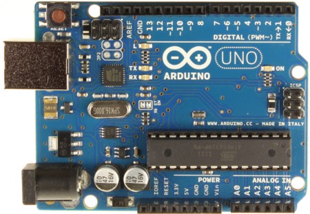
Arduino Uno Board
The board features an Atmel ATMEGA328 microcontroller operating at 5 V with 2 kb of RAM, 32 kb of flash memory for storing programs and 1 Kb of EEPROM for storing parameters. The clock speed is 16 MHz, which can translate to execute around 300,000 lines of C source code per second. The board also consists of 14 digital I/O pins (of which 6 can be used as PWM outputs), 6 analog input pins, 6 power pins, an ICSP header and a reset button. There is an USB connector which can be connected to the host computer and a DC power jack for connecting an external 6-20 V power source.
A control program can be created on the host PC, then it can be downloaded to Arduino and will run automatically. It also allows you to develop and debug your program. The Arduino programming language is a simplified version of C/C++. The codes written for Arduino are called “Sketches”.
These sketches contain two “void” functions namely, setup() and loop(). Under the setup() function you can do any initialization steps. This method is run once just after the Arduino is powered up. The loop() method is run continuously afterwards and in here you type codes that should run many times.
Our project
Aim of our project is to create a temperature detector system that reads the temperature from a temperature sensor every three seconds and displaying it on a LCD. In addition the data taken are stored in a SD card and can be retrieved as well. Pushbutton1 enables data to be displayed in the serial monitor and the LCD back light is switched On and OFF by the pushbutton2.
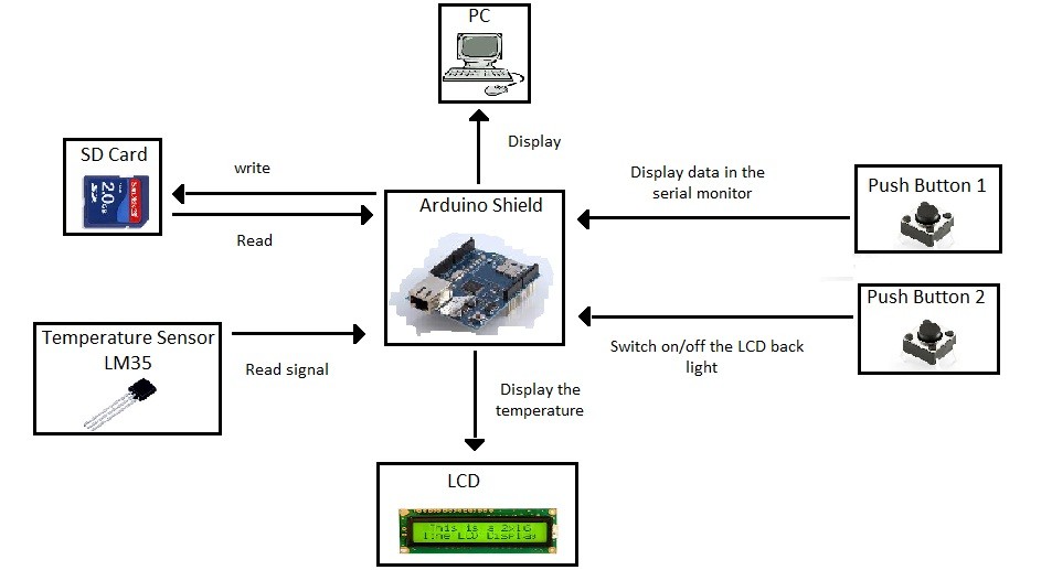
Block Diagram of the project
Hardware required
- Arduino Uno board
- LCD
- Push buttons
- LM35
- SD card and a LC studio board
- 10K resistors
- 1.8K resistor
- 3 V Zener diode
- npn transistors
Circuit
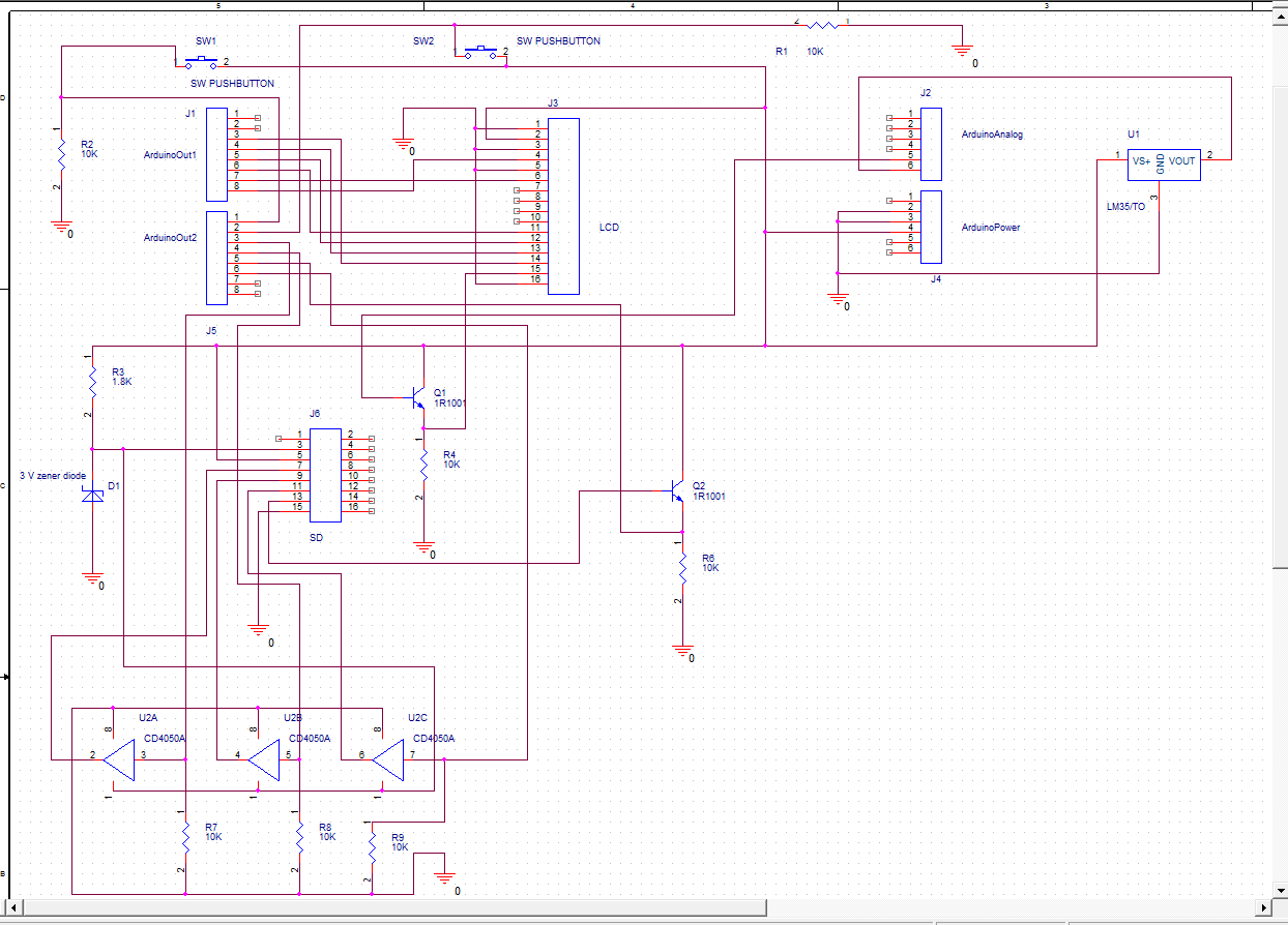
In the Arduino board pins 2-7 and pin A1 are used to interface the LCD. Pin 10, 11, 12 and 13 are used for the SD card. Pin 8 and 9 are used to interface the push buttons and Pin A0 is for temperature sensor (LM35).
LC studio board is used to interface the SD card. Since Arduino board gives an output voltage of 5 V, a buffer is used to reduce it to 3 V before connecting it to the pins in LC studio board. IC CD4050BC is used for this purpose. D10 is connected to the CS pin of the LC studio board. Also D11 to MOSI, D13 to SCK and D12 to MISO are connected through the buffer.
Push buttons are connected to relevant I/O pin (D8 and D9) and grounded through a 10K resistor. The other side of the buttons are connected to the 5 V output of the Arduino shield.
Supply voltage for LM35 is connected to the 5 V output of the Arduino board. Output is connected to the analogue in A0.
Pin Vss of the LCD is connected to the ground terminal. And the supply voltage is 5 V. V0 and R/W pins are also connected to the ground terminal. Rs is connected to D7. E is connected to D6. D4 of the LCD is connected to D5. Also D5 to D4, D6 to D3 and D7 to D2 are connected respectively. A1 pin is used to control the black light of the LCD.
Schematic
Code
</pre>
int led = A1;

int btn = 9;

int btn2 = 8;

int buttonState = 0;

int buttonState2 = 0;

int ledState = 1;

int mins = 0;

int DRT = 0;

int DRTINIT = 0;

// include the library code:

#include

#include

// initialize the library with the numbers of the interface pins:

LiquidCrystal lcd(7, 6, 5, 4, 3, 2);

// default chip select pin is set to digital 10:

const int chipSelect = 10;

File myFile;

void setup() {

// Begin serial communication at 9600 bits per second:

Serial.begin(9600);

//Defining input and output pins:

pinMode(led, OUTPUT);

pinMode(btn, INPUT);

pinMode(btn2, INPUT);

pinMode(10, OUTPUT);

digitalWrite(led, HIGH);

lcd.begin(16, 2);

//Check whether the card is available:

if (!SD.begin(chipSelect)) {

lcd.print("Card failed");

// If the card is absent an infinite while loop is run:

while(1);

}

// set up the LCD's number of columns and rows:

// (note: line 0 is the first row and line 1 is the second row)

// Print the temperature and time to the LCD at the defined rows and columns:

lcd.print("Temp:");

lcd.setCursor(11, 0);

lcd.print("'C");

lcd.setCursor(0, 1);

lcd.print("Time:");

}

//Controlling LCD back light:

//If the back light is high set it to low and vice versa once the pushbutton1 is pressed:
void loop() {

buttonState = digitalRead(btn);

buttonState2 = digitalRead(btn2);

if( buttonState == 1){

if (ledState == 1){

digitalWrite(led, LOW);

ledState = 0;

delay(500);

}

else if (ledState == 0){

digitalWrite(led, HIGH);

ledState = 1;

delay(500);     //To avoid debouncing

}

}

lcd.setCursor(5, 1);

int frac = millis()/1000;     // Convert milliseconds to seconds:

int sec = frac - (mins*60);

mins = (frac)/60;            // Convert seconds into minutes:

lcd.print(mins);

lcd.print(" : ");

lcd.setCursor(8, 1);

lcd.print(sec);

if(sec == 0){

lcd.setCursor(9, 1);

lcd.print(" ");

}

// read the input on analog pin 0:

int sensorValue = analogRead(A0);

// Convert the analog reading (which goes from 0 - 1023) to a voltage (0 - 5V):

float voltage = sensorValue * (5.0 / 1023.0);

float temperature = 100*voltage;

// print out the value you read in the 5<sup>th</sup> column on the 1<sup>st</sup> row:

lcd.setCursor(5, 0);

lcd.print(temperature);

//Check the availability of the file datalog4.txt, collect data and write them onto it:

int temp = frac/3;

DRT = temp-(DRT*3);

if(DRT > DRTINIT){

File dataFile = SD.open("datalog4.txt", FILE_WRITE);

//If the file is available, write to it:

if (dataFile) {

dataFile.println("Time : ");

dataFile.println(sec);

dataFile.println("Temperature : ");

dataFile.println(temperature);

dataFile.close();

}

DRTINIT = DRT;

}

//Display the data on the serial monitor when the push button2 value is high:

if( buttonState2 == 1){

myFile = SD.open("datalog4.txt");

if (myFile) {

Serial.println("datalog4.txt:");

// read from the file until there's nothing else in it:

while (myFile.available()) {

Serial.write(myFile.read());

}

// close the file:

myFile.close();

}

}

}
<pre>
Discussion
The above circuit is constructed to obtain the ambient temperature for every 3 seconds. Data is initially stored in the SD card and displayed on the LCD. Once the relevant push button is pressed, data in the SD card is sent to the serial monitor and displayed there.
It was essential to input 3 V to the VDD of the IC CD4050BC. In the initial circuit this was obtained using a voltage divider where 5 V was divided between a 1.8K and a 3.3K resistor. The voltage across 3.3K was connected to VDD. But once the cicuit is built , the voltage across the 3.3K resistor was more than the expected value. Therefore the circuit was modified by replacing it with a 3 V zener diode.
It should be noted that the 3.3 V logic voltage level needs to be maintained or else it can cause the SD card to card stop working. Therefore this circuitry is of paramount importance.
Working with the arduino environment was easy. Example libraries were very useful. It was possible to use these examples other than typing the code from the beginning.
In the initial code when the time reached 60 the loop starts from the beginning and the last digit stayed there. This results 1s to display as 10s. This keeps occurring until the time reaches 9s. After that the time was displayed correctly. To avoid this the curse was set using the “setcurser “
Earlier the LCD display started blinking since the data was read constantly. Therefore the code was modified to read data with a delay.
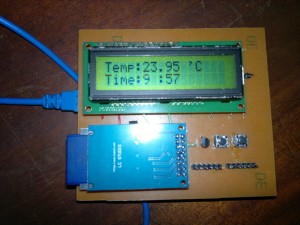
Top view
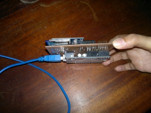
viewed from the side
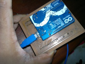
Bottom view