Introduction
The project which is going to be introduced here is a Kitchen Timer which can be used with many of our day to day activities. A timer is a specialized type of clock. A timer can be used to control the sequence of an event or process. When the set period expires some timers simply indicate so, while others operate electrical switches, such as a time switch, which cuts electrical power. Most of the cases the indication may be an audio signal. In the device which has been given, the above mentioned both abilities are available. It has the ability of giving an audio signal at a given time and the ability of switching off the circuitry after few minutes of counting down the time. To indicate the time it uses a Seven Segment Display (SSD) and the mechanism of the relay systems are used to switch off the circuitry. In this case the power will cut off from the wall socket and all the equipments which are connected to the same wall socket will automatically turn off. To take up the challenge it has been used a 16F877A type microchip which is programmed up to the level which can perform the expected functions. The programming part it is done with HITEC C and if the user need to do the further modifications it is also can be done very easily by adding the extra items to the device.
High Level Design
The main purpose of this device is switching off any electronic or electrical equipment which is connected to the device. In the tour of achieving this goal it is needed to identify what are the options should be included in to the system.
- User Adjustability an Displaying the results
- Micro Switches And Seven Segment Displays
- Audio Signal handling
- Buzzer
- Switching Off
- Relay
In most of the previous designs only the buzzer had been included. But in this case both switching off and buzzering options have been included. At the beginning I was thinking of using a LCD module to display the data adjusted by the user. But at the end it was decided to go ahead with SSDs. To achieve the goal successfully the complete circuit was designed with five parts. Those are as follows.
• Main Circuit
• 4-Digit Seven Segment display
• Switch Board
• Power Supply
• Relay and Buzzer
Main Circuit
Main circuit consists with most of the parts such as PIC voltage regulators etc. All the other sections are interconnected with this Main circuit. The signals which are needed to run the Seven Segment Display, Relay and the Buzzer are supplied through this main circuit.
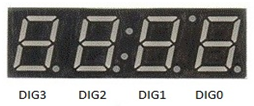
4-Digit Seven Segment display
Seven segment displays can be controlled through the PIC very easily and the same principle which is used in counter circuits can be used in this case too with some further modifications. 4-Digit Seven Segment display is used to display the down count of the adjusted time. In this case two digits are used for minute’s section and two digits are used for second’s section. When the circuit is turned on the display will show 00.00 and this position allows user to adjust the time required.
Switch Board
Switch Board is used to input data to the circuit. This is the interface between the user and timer circuit. The switch board consists with 6 switches. Push buttons has been used to construct the Switch Board. The user can easily enter data using those push buttons. The data which are input are displayed on the Display at the real time.
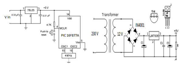
Power Supply
To drag the power to run the circuit a transformer with an output of 12 V and 300 mA has been used. Diode bridge circuit has been included to the power supply to gain a better current.
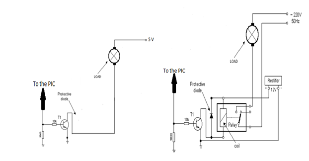
Relay and Buzzer
When the down count is in progress it is needed to give an idea to the user about the remaining time. To achieve this goal a Buzzer has been used. The equipment which is needed to control through the device is connected through the Relay. At the end of the down count the power is cut off from the equipment which is connected through the Relay.
The following Table shows how the Ports have been used.
| Port | Pin | Task | Port | Pin | Task |
| B | 0 | A | C | 0 | Dig 0 |
| SSD | 1 | B | Digit | 1 | Dig 1 |
| DATA | 2 | C | Select | 2 | Dig 2 |
| 3 | D | 3 | Dig 3 | ||
| 4 | E | ||||
| 5 | F | D | 0 | START | |
| 6 | G | Switches | 1 | Dig 1 UP | |
| 7 | H | 2 | Dig 1 DOWN | ||
| E | 0 | Buzzer | 3 | Dig 2 UP | |
| 1 | Relay | 4 | Dig 2 DOWN |
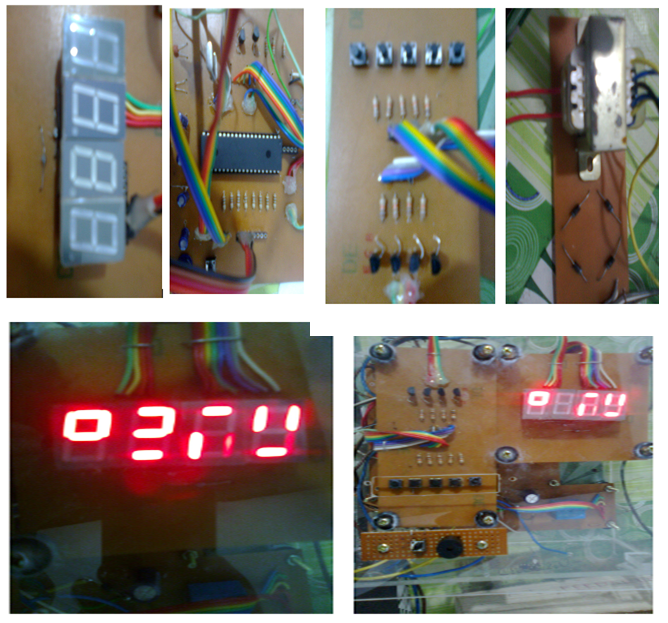
Hardware Construction
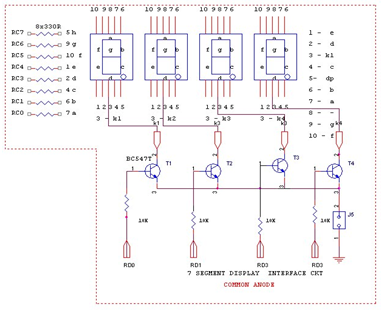
At the very first stage of hardware construction I decided to construct the hardware part which is relevant to the display. In this case 4 Common Cathode SSDs are used. To handle them BC 547 transistors and 10 K resistors are used. For the data lines 100 Ω resistors are used. Digit selecting is as follows.
Hardware construction for the SSD
Hardware Contruction for the Buzzer and Relay
For both Relay and the buzzer BC 547 transistor can be used and the resistor value ia 10 K.
Hardware Construction for the Power Supply
Caps which have been used here has the value 47 mF. In addition to the LM7805 another voltage regulator LM7812 had to be used to drive the relay.
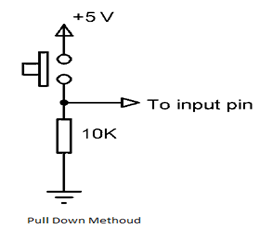
Hardware Construction for the Switches
To construct the switching board 10 K resistors have been used with the micro switches.
Software Handling
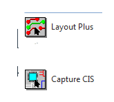
There are number of software available for PCB designing such as EXPRESS PCB, ORCAD, and EAGLE etc. In this project the Hardware part is developed and designed with ORCAD. Schematic diagram was drawn in the ORCAD Capture CIS and the PCB design was done in the ORCAD Layout Plus. This is the software which is used by many of the professionals in the field.
All the codings which are needed to run the system have been done with HITEC C language in MPLAB 7.5 Version. I have given the source code in the attachments.
Results
Process taken out in the device
- Connect the Equipment to the timer
- Turn the power on
- Make the time adjustments
- Press Start Button
- Buzzering at the position 02.00 (Two minutes are remaining) and 00.10 (Ten seconds are remaining)
- Turn the Relay Off at the position 00.00 (Time is over)
- Stop the Downcount
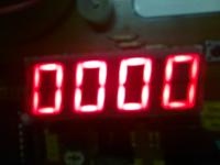
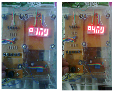
When the device is ready for the adjustments the display will be like this.
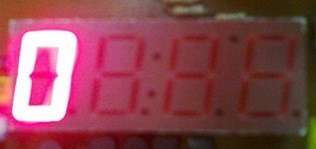
When the downcounting is over the display will come to the position which is shown in the following diagram.
Further Improvements
- Adding more SSDs
In this case more SSDs can be added to the system to indicate Hours , Minutes and Seconds. Then the maximum adjusting time can be increased.
- Adding more switches
By adding more switches the number of functions which can be performed can be increased.
Ex: Time adjusting for the Seconds section.
Making the adjustments while the down counting is in progress.
- Using a key pad instead of a few micro switches to make adjustments
By using a keypad the figures which is needed to enter to tha system can be entered directly. Then the time wastage for making the adjustments can be minimized.
Appendix
Components List
| Component | Quantity |
| PIC 16F877A | 1 |
| PIC IC Base | 2 |
| Resistors 100 Ohm | 8 |
| Resistors 10K | 15 |
| Transistor BC547 | 8 |
| Relay 12 V | 1 |
| LM 7805 | 1 |
| LM 7812 | 1 |
| Common Cathode SSD | 4 |
| Diodes IN4001 | 5 |
| Micro Switches | 6 |
| Transformer 230V to 12V | 1 |
| Crystal Oscillator 4MHz | 1 |
| Capasitors 22pF | 2 |
| Capasitors 47mF | 4 |
| Capasitors 470 mF | 1 |
| Buzzer | 1 |
| Connector Bar | 1 |
| Ribbon Wire |
Photo Gallery

References
- Ibrahim, D (2006) PIC BASIC Projects: 30 Projects using PIC BASIC and PIC BASIC PRO, London: MPG Books Ltd.
- Hellebuyck , C (2003) Programming PIC Microcontrollers with PIC BASIC, Burlington: Elsevier Science.
- http://avtanski.net/projects/timer/index.html
- http://embed4u.blogspot.com/2009/10/pic-microcontroller-16f877a-schematic.html
- http://www.micro-examples.com/public/microex-navig/doc/084-alarm-clock
- http://www.mikroe.com/old/books/plcbook/plcbook.htm