Introduction
What is reflectance?
Reflectance is a property of a surface which is equal to the proportion of incident light which it reflects or scatters. It describe about the surface’s nature. That is whether it is a rough or smooth one or it is a dark or light one. Reflectance is a very important fact in Physics, especially in optics and also in wave theory as well.
What is this?
LED Reflectometer is a device which used to measure this property. Mainly it transmits pulses of LED light into the environment, and monitors the strength of the LED light reflected back from objects nearby. This instrument can transmit different pulses and can detect the reflected signal and can show the difference between those two signals. These two values used to measure the reflectance of that surface. The reflectance is a fact that is varying with the properties of the surface and that can be changed with the colour of the LED light beam.And this project is based on PIC micro controllers.
Methods in use
- Microwave reflectometers
- Infrared (IR) reflectometers
- Optical reflectometers
- Time Domain reflectometers
Advantages
Using the LED reflectometer, relative reflectance of any material or surface can be determined by pointing the device toward the target material from a short distance away and gauging the brightness of the LED in comparison with other targets tested at approximately the same distance.
Not only that, since we are using different types of LED s here, we can see the reflectance of different colors from the same material and this will allow us to compare the sensitivity of each and every color with others.
Design
Hardware:
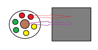
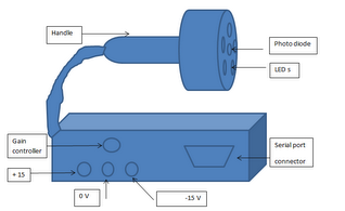
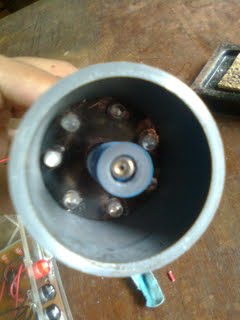
The device basically consists of two parts:-
- A Transmitter(LEDs) and
- A Receiver(Photo Sensitive Diode)
This diagram shows the basic design of the reflectometer.
Software:
The software which are used to construct the system are MPLAB, winpic80…C language used to write the algorithm according to the constructed design.
Methods used
ADC
In this Reflectometer the reflected signal from the surface is passed through the photodiode and it is an analogue signal. Since it is needed to convert this analogue signal to a digital signal I here used analogue to digital converter. In PIC16F877A microcontroller one can find two ports that can perform this task. Those are port A and port E. From these two ports I have used pin number 2 of port A to convert the detected analogue signal to a digital signal.
Current drivers
This system needs to drive current through it without annoying to the components which are very sensitive to the current and voltage variations. To overcome such problems I have used a special part called ‘current drivers’ to the circuit. LM317 is the current driver that I have selected to perform this task.
Voltage Regulators
This device has different types of components which needs different values of voltages to work properly. For example photodiode is in working condition when its reverse voltage is nearly equal to 10 volts, and the operational amplifier TL084 needs +15 volts and -15 volts as its supply voltages. MAX 232 integrated circuit needs +5 volts for its action and so on. To fulfill all these needs I used voltage regulators in my circuit.
7805 to produce +5 V
7810 to produce +10 V
+15 V, 0V and -15 V are given to the circuit and those are converted to the other needed voltage values through voltage regulators.
Amplifying circuit
Here had used a more sensitive photodiode which can produce a voltage when the photo cells are fallen on its surface. But the voltage generated by this is a very low value. Because of that I used an amplifying circuit with it and it can amplify the reflected signal and that is the output voltage.
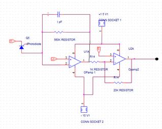
Here I have used two TL084 operational amplifiers. And from first operational amplifier the reflected signal will amplify and since these operational amplifiers are connected in as inverting amplifiers it gives a negative voltage. I have to use another amplifier with the same inverting conditions to take a positive voltage as the output. The gain of the second amplifier is set to 20 by selecting the feedback resistor of value 20Kilo ohms and the other resistor as 1Kilo ohms.
A capacitor which has a value of 1 pF is connected between the output pin and the inverting input pin of the first amplifier to smooth the shape of the reflected signal.
Serial port connector and MAX 232
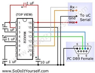
Serial port of the computer can connect to the PIC microcontroller through MAX 232 integrated circuit as showing in the following figure.
Results
Results of the reflectometer will be given on a computer screen when it connects to a computer through a parallel port.By analyses those with the aid of MATLAB software we can come to conclutions about the surface.
Images
Applications
Can be used in experiments when one need to measure the reflectance of a surface and when one need to describe the properties of a surface
References
- www.sodoityourself.com
- www.wikepedia.com
Lyssi_ Daniel, Institute of Computer Science II, University of Bonn, Germany.
Appendix 1
Schematic Diagrams of the circuits
Schematic diagrams of the circuits can be downloaded from the attachments
Appendix 2
Program of the Reflectometer
This one is also can download from the following attachment menu
Appendix 3
Component List
| Component | Quantity |
| PIC 16F877A | 1 |
| LM 317 | 3 |
| LED s | 7 |
| Resistors 330 ohms | 7 |
| TL 084 | 1 |
| MAX 232 | 1 |
| LM 7805 | 1 |
| LM 7810 | 1 |
| Transistor BC 108 | 7 |
| Resistors 24 ohms | 1 |
| Resistor 40 ohms | 1 |
| Resistor 60 ohms | 1 |
| Serial port connector | 1 |
| S 5971 photodiode | 1 |
| Resistors 20 K ohms | 1 |
| Resistor 1 K ohms | 1 |
| Resistor 560 K ohms | 1 |
| Variable resistor 10 K | 1 |
| Capacitor 20 pF | 1 |
| Capacitor 1 uF | 1 |
| Capacitor 10 uF | 1 |