Introduction
Motion detecting twilight LED lamp is design to turn ON & OFF the light in a room with the use of motion sensor. When a person go through the door inside to the room he or she may forgot to turn off the light when leaving the room. This happens very frequently in our day today life, increasing the expenditure of the light bill.
Since the electricity has becoming a critical factor in both industrially and domestically, the consumption of electricity should be done in a proper controlled manner. Therefore a system kind of this would be very important and helpful in preventing that kind of a problem.
High Level Design
Logical Structure

The central element of this system is the PIC 16F877A Microcontroller . It continually takes in information from the Infrared Sensors (IR) and the Light Sensors (LDR) to make decisions on the LED lamp whether it is turning ON or OFF.
The Infrared Sensor, mounted on the doors of the room, communicate to the microcontroller when they are toggled, indicating that somebody passed through the door.
The light sensor is a LDR (Light Depending Resistor) mounted inside the room. It is connected to the microcontroller’s Analog-to-Digital Converter to provide a numeric interpretation of the amount of light inside the room.
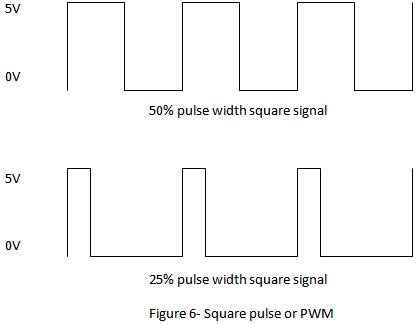
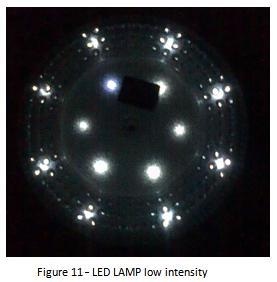
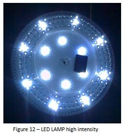
The brightness of the LED lamp is controlled by the PWM where the pulse width of the square signal which is taken out from the PIC is controlled by the two pushbuttons.
Two Push buttons are implemented, that communicate to the microcontroller when they are toggled, indicating that the button was pressed. The button presses are used by the microcontroller to determine whether it should operate the LED lamp to increase the intensity of it or to decrease the intensity of it.
Operation
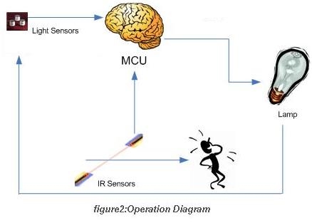
This is a system that automatically controls the light in a room based on room occupancy, lighting conditions and user objectives by controlling the intensity of lighting inside and the amount of external light coming into the room.
Following are some activities of the system under certain conditions when the room is in,
- Bright light
- LED lamp won’t turn on saving the energy.
- Dark
- Once the first motion detected by the IR (walking into the room)the lamp would turned ON and after the second detection of IR (walking outside from the room)the lamp would turned OFF.
Hardware & Software Designing
IR Motion Detection
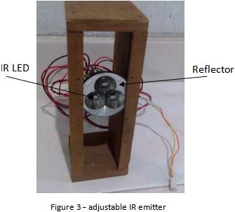
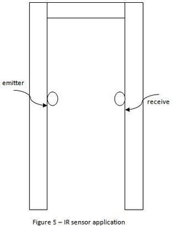
An IR motion detector circuit is build using a infrared transceivers (Receiver: TSOP1738; Transmitter: IR LED).Three IR emitter LED s are used for resulting a good sensing at the receiving end. A reflector is used to make an approximate align in a straight line of IR beam. The most important thing is to adjust the IR LED in a straight line with the IR receiver. These two units should be build to the both side of the grill as shown below.
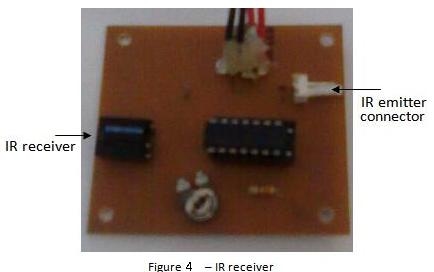
Here the IR emitter should modulate to 38kHz frequency in order to detection (because the IR receiver sensitive only for that frequency -refer the datasheet-). Here the out put of the IR receiver when the motion is detected goes 5V to 0V. In order to have an inverted signal an inverting comparator LM324 multioperational amplifier circuit is used for that.This design permits easy interfacing with the microcontroller as it provides an active-high signal to indicate a specific sensor has toggled.
The transmitter/receiver pair has an active range of detection of about 10° and were tested for acceptable operation of 0.75m.
Dimming LED Lamp
Part of setting the right ambience in a room is controlling the intensity of the lights. Very bright lights have a much different effect on people than low lights. Dimming can be achieved in different ways, the most straightforward being a variable resistance that varies the current coming in to the lamp. However, variable resistance dimming is very inefficient in terms of energy, as the resistance is turning energy into heat that is not used.
An efficient way to dim an LED Lamp is to use a periodical square signal in different square pulse width. For that software PWM in microcontroller is used with to push button. Push buttons are used with pull up resistors. Where the one button increase the pulse width (increasing the intensity of the lamp) and the other button decreases the pulse width (decreasing the intensity of the lamp). Here the pulse width out put port was input to the lamp through the transistor.
Twilight sensor
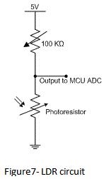 An LDR (Light Depending Resistor) is used to measure the intensity of light inside the “room”. This light dependent resistor is an electronic component whose resistance decreases with increasing incident light intensity and vice-versa. This module was connected with another resistor is series in the form of a voltage divider . The output of the voltage divider was connected with the Analog-to-Digital Converter input of the microcontroller to acquire the various voltage levels.
Since the resolution of the microcontroller’s ADC is 8-bits, the ‘digitized’ output of the voltage divider ranges from 0 to 255 units. Digitizing is used only to decide weather the inside light is bright or dark.
Power Supply
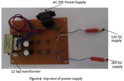
In constructing the power supply unit step down 230 to 12 tap transformer was used. The 12V was used to input to the 7805 regulator which gives a 5V to the PIC IC and the 24V was used through the LM317 regulator to the led lamp. Here the power supply out the dc voltage.
The Main Board
This contain the mainly the microcontroller with the LDR,
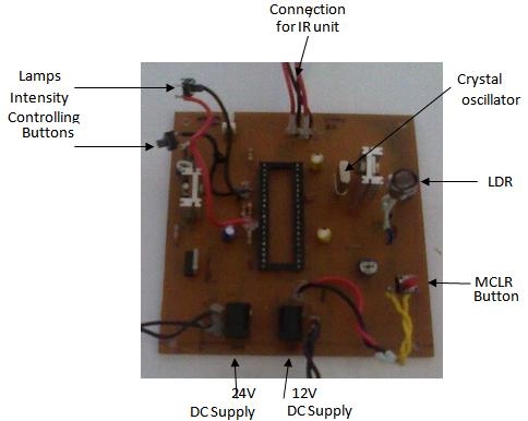
Figuer10-main board
Component List
Table1-component list
| Component | Description | no |
| PIC16F877A | microcontroller | 1 |
| TSOP1738 | IR receiver | 1 |
| IR LED | IR led | 3 |
| 4 MHz crystal | crystal oscillator | 1 |
| 22 pf | capacitor | 2 |
| 0.1 uf | capacitor | 1 |
| 1 uf | capacitor | 1 |
| 10 uf | capacitor | 2 |
| 1000 uf | capacitor | 2 |
| 1k preset | potential divider | 2 |
| LDR | light depending resistor | 1 |
| 1k | resistor | 3 |
| 10k | resistor | 1 |
| 33 ohm | resistor | 1 |
| c828 | transistor | 1 |
| D313 | transistor | 1 |
| LM7805 | regulator IC | 1 |
| LM317 | regulator IC | 1 |
| push button | push button | 3 |
| IN4001 | diode | 8 |
| lm324 | comparator opamp | 1 |
Software
Here is the simple algorithm used to build this up,
If input port=0 (low detect the person enter to the room);
{
If LDR input port=1 (dark);
Turn on lamp;
Else turn off lamp;
}
Else go to line 8;
If input port =0 (detect the person leave the room)
{
Turn off lamp;
Go to line 1;
}
Else turn on lamp;
While led turn on
{
Push buttonin=1 (press of the push button to increase the brightness of the led lamp)
Increase the duty cycle of PWM;
Push buttonde=1 (press of the push button to decrease the brightness of the led lamp)
decrease the duty cycle of PWM;
}
The Firmware
The MPLAB IDE was used to write down the PIC C code and HI TECH PIC C Compiler used to debugging the code. Win PIC800 v3.64 was used to program the PIC IC 16F877A for driving AC relay controlling circuit.
Results
Under dark the LED lamp turned on according to the LDR .
The code is lightweight and does not crash the microcontroller, which suggest a smaller microcontroller could be used in an upgraded version of the system, or more features can be easily added to the system.
The push button used for LED lamp intensity controling controls the intensity of it.
The first detection turn on the LED lamp if inside is dark
The second detection turn off the LED lamp.
Conclusion
Here Lm317 could be used as good current source and a voltage source. But it couldn’t use the both at the same time. The current and the voltages could be adjusted by varying the resistor values.
IR receiver TSOP 1738 was a receiver sense only for the Infra Red at the frequency of 38 kHz. So to sense well the IR LED should modulate to the 38 kHz frequency. Uses of reflectors make the IR Beam approximately in a straight line.
By using the PWM pulse width modulation a signal having a particular frequency could be generated. In the 16f877 there were two pins for the PWM module. But both pins couldn’t be used to generate the different types of frequencies.
Here the motion detection system could be improve more by using two IR sensors, to find out the direction of the motion.
References
- Michael Bluejay (1998-2011) saving energy on light [Online], Available:
http://michaelbluejay.com/electricity/lighting.html
[28 march 2011] - www.electronic-circuits-diagrams.com (2010) [Online], Available:
http://www.electronic-circuits-diagrams.com/lightsimages/lightsckt4.shtml
[28 march 2011]