Introduction
In day to day life security of any object or place is plays a major role. This project has considered about that and created a secure access for a door which needs a password to open the door. Using keypad it enters a password to the system and if it is entered correctly door is open by motor which is used to rotate the handle of the door lock. It will give three attempts to enter the password when it is entered incorrectly at the first time. Some features like adding new users and changing old password are configure by the keypad.LCD module is used to display messages to the user.
Materials and Methods
Basically to construct this device it is used ATmega 328 microcontroller, 4×3 number keypad, 16×2 character LCD module , vehicle center lock motor and power supply unit.
ATmega 328 microcontroller
In here it used ATmega328 microcontroller. This is the heart of the system. It is a 28 pin 8 bit microcontroller with 23 input/output peripherals.From this microcontroller it is used all the 3 port registers for my work.it is used register B for interfacing LCD module and register D for interfacing the keypad. Port C pin number 4 and 5 have used to send a signal to activate a motor to open and close the door.
And also it is used internal EEPROM (Electronically Erasable Read Only Memory) which is a non volatile and having reasonable long lifespan, to store entered passwords. Since it is a non volatile it can store information when there is no power to the microcontroller too. In ATmega 328 microcontroller it has 1Kbyte memory space for the EEPROM. That means it has 1024 bytes for storing data. EEPROM has mainly 3 registers naming EEPROM Address Registers, EEPROM Data Register and the EEPROM Control Register. We can write and read data to/from the EEPROM by calling functions which are related to the EEPROM registers.
Below is the pin diagram of the IC.
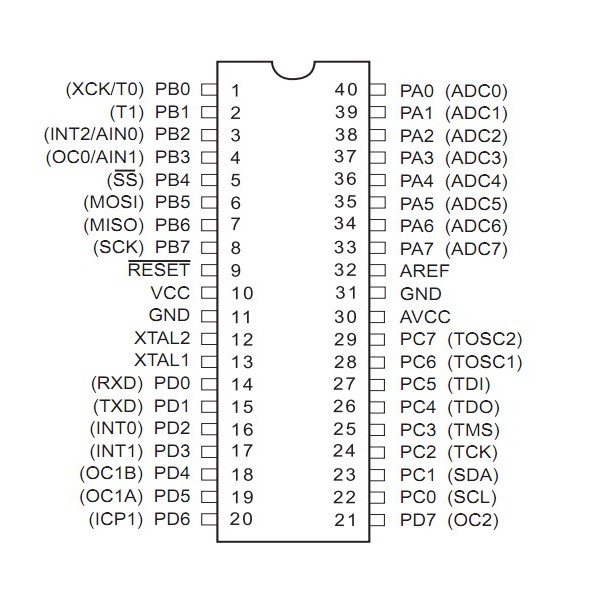
Figure 1- Pin diagram of ATmega 328P Microcontroller
4×3 number keypad
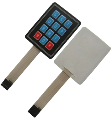
Figure 2- Image of 4×3 keypad
Here it is used 4×3 matrix keypad to enter passwords for accessing Door lock.In here it has been interfaced keypad as below to the Port D register of the microcontroller. R1, R2, R3 resistors are used to activated internal pull-ups. Keypad is like a 4×3 matrix which have rows and columns. Each key is act as an opened switch, when it pressed any key path will completed and current is going through. Pins of Port D then read that changing signal and read assigned value to that key and output it.

Figure 3- Interfacing 4X3 keypad to the Microcontroller port D
16×2 LCD (Liquid Cristal Display) Module
LCD is used to display massages to the user when he is pressed any key. LCD has a separate header file which includes functions and commands to write us on LCD. Therefore when we are using LCD module we have to import its header file lcd.h to our main code. Below is the pin diagram of LCD.
LCD pin configuration:
- VSS (GND Supply)
- VCC (+5V)
- VEE (Contrast Adjust)
- RS (register Select)
- RW (Read/ Write)
- E (Enable)
- DB0
- DB1
- DB2
- DB3
- DB4
- DB5
- DB6
- DB7
- LED +
- LED-
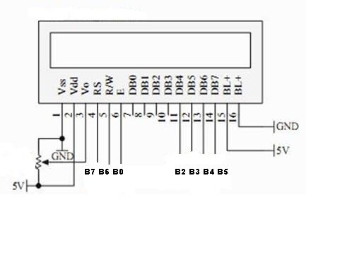
Figure 4-Interfacing LCD module to the Microcontroller port B
Center Lock Motor
This is a vehicle door locking motor which work with 12V DC voltage supply. By Changing voltage to the input terminals of the motor, stick which is connected to the motor can be move outside and inside. By clamping a clip to the door handle and other end to the stick of the motor it can be made the door handle to be rotated to unlock the door when motor is powered.
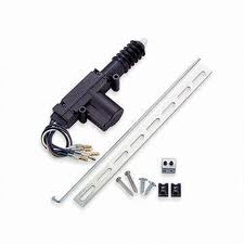
Figure 5- Center Lock Motor
Power Supply Unit
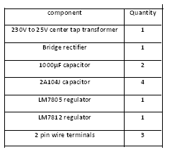
it is needed the microcontroller D/C 5V to work on and D/C 12V to the motor to work on.since this device is plug in to the 230V main power supply it has to step down that 230V to the below value and it is needed separate to power supplies to the microcontroller and to the motor.therefore separate 5V and 12V regulator circuits are embedded to this power supply unit with 230V to 25V step down center tap transformer.
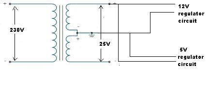
Figure 6-Basic diagram of power supply unit
Design and Construction
below is the diagram of showing how the main components are gather together to do a task.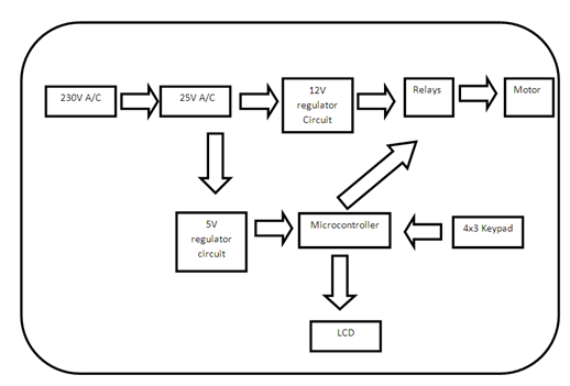
Figure 7- Main block diagram of the system
Motherboard
This motherboard contain all the components like LCD, Keypad,ATmega 328 microcontroller, USB connector socket, wire connectors etc.Schematics diagrams of motherboard and power supply unit are attached in the Appendix A and list of components for both are attached in the Appendix B.
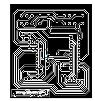
Figure 8- PCB layout of the Motherboard
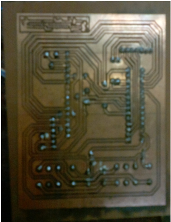
Figure 9- Motherboard after etching and soldering
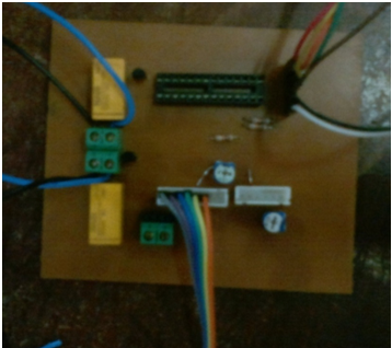
Figure 10-Complete motherboard circuit
Software design
The basic concept of software design is it should scan the pressed key values by the microcontroller and according to that signal change of the port D it return which key has pressed and check whether that entered 4 digit password and stored password in the EEPROM are matching. If they will match motor is activated and door is opened.
Results and Analysis
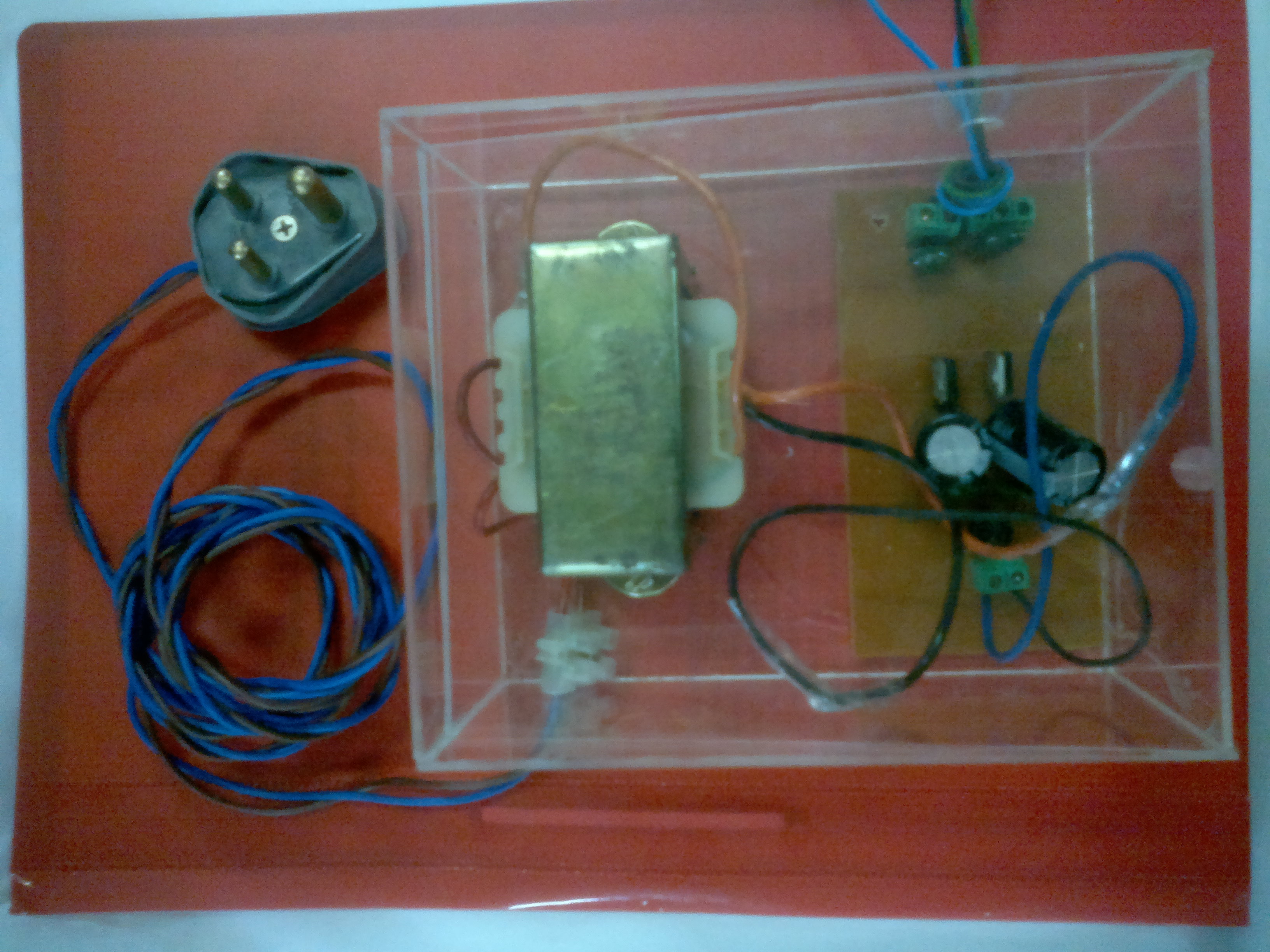
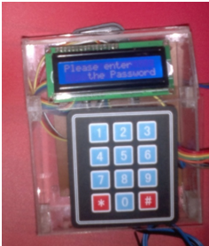
Figure 11- Final output of the power supply unit and main box
- Initially LCD module is displaying a message “please enter the password”.
- 1-9 keys can be used to set passwords.
- When it is entered a 4 digit password by the user it will display on LCD as “****”. Therefore anyone else can’t see what the user enters.
- If it is the correct password, LCD displaying a message “Well come” and the door will be opened.
- After 1minuts time door is locked automatically.
- If it is entered password incorrectly LCD displaying “password error”
- If it is a wrong password user received another 3attempts to enter the correct one. If he couldn’t enter password correctly by these attempts he have to wait 3 minutes time more to re logged in to the system.
- After opening the door if user wants to change his password, after pressing “0” key and giving user id user can change his password.
- If user wants to add more people to the system after opening the door pressing “#” key, user can add more users. System will give user id to each password.
- 10 users can be added to this system.
- When it make any mistake while entering the password user can delete it by using “*” key.
Future Enhancements for Device
- It can develop the system with including ibutton reader. then user can unlock the door by using keypad as well as ibutton too. http://www.maximintegrated.com/products/ibutton/ibuttons/
- since this device is working with external power source if there is a power cut system will be down.for that it is better if it include internal power source for the device to work when it is no external power.
Bibliography
ATmega 328 datasheet: http://www.atmel.com/Images/doc8161.pdf
LCD module: http://extremeelectronics.co.in/avr-tutorials/using-lcd-module-with-avrs/
Keypad Interfacing: http://atmega32-avr.com/4×4-keypad-example-using-avr-gcc-c-language/
ibutton reader: http://www.maximintegrated.com/products/ibutton/ibuttons/
DPDT relay: http://www.engineersgarage.com/electronic-components/dpdt-double-pole-double-throw-relay
EEPROM: http://deans-avr-tutorials.googlecode.com/svn/trunk/EEPROM/Output/EEPROM.pdf
Appendix A
Schematics diagram of the motherboard
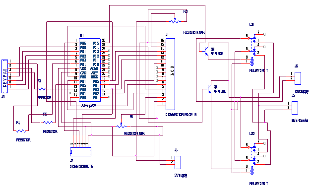
Figure 12- Schematic diagram of motherboard circuit
Schematics diagram of the power supply unit
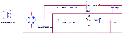
Figure 13-Schematic diagram of power supply
Appendix B
Components list
Table 1-Motherboard component list
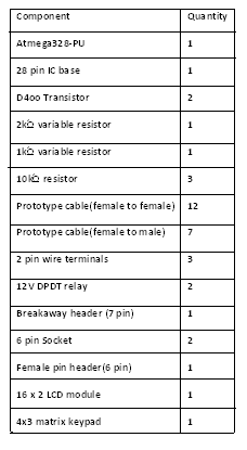
Table 2- power supply component list