INTRODUCTION
LED display notice board is an economical solution for displaying messages with various changing effects. It is applicable in shops, restaurants, pharmacies and etc . These notice boards can be made in large led panels or led dot matrix displays. They are in mono color , bi color and multi color. Power consuming of led display notice boards are also less.
On this project six led dot matrix displays were used in red color. They were interfaced using max 7219 according to serial programming interface communication. Led display notice board can display static and dynamic messages.
MATERIALS AND METHODS
led dot matrix
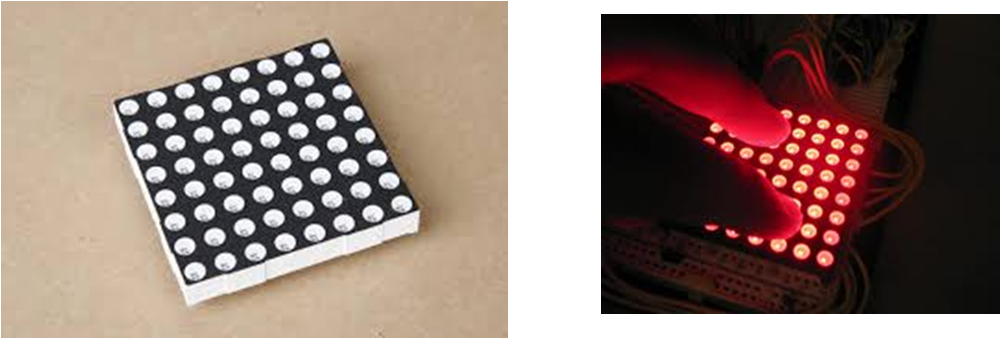
LED dot matrix is used to display some information . Generally 8×8 ,7×5 LED dot matrix are common to see . They are in mono color , bi color and multi colors . There are two types of LED matrices.
LED MATRIX DISPLAY
- Common anode type
- Common cathode type
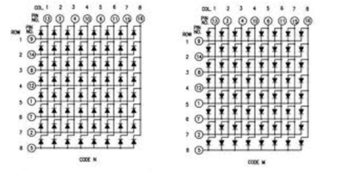
COMMON CATHODE AND COMMON ANODE LED MATRIX
On this project the message displays on six LED dot matrix displays . Common cathode LED matrix displays are used in this project. Used LED dot matrix display has 64 LED s as 8×8 array . A letter can be displayed in one LED matrix .
SPI COMMUNICATION
SPI means Serial Peripheral Interface. In SPI communication less I/O pins are needed. SPI used to communicate with AVR and other devices such as EEPROMs and ADCs. It is very fast between two or more devices. On SPI communication we need 4 pins to specify four logic signals.
- SCK – serial clock
- MOSI- master output slave input
- MISO –master input slave output
- SS – slave select
| NAME | OTHER NAME |
| SCK | CLK |
| MISO | SOMI, SDO, DO, SO |
| MOSI | SIMO,SDI ,DI ,SI |
| SS | CS, CSB, CSN ,STE |
MASTER SLAVE CONNECTION
On SPI communication one master device and one or more slaves. Master device control the communication and slave devices receive the data from master and transmit to the master device. The both master and slave devices have 8 bit shift registers. Master device generates a clock pulse.
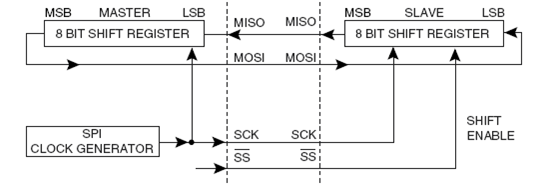
MASTER AND SLAVE DATA TRANSFER
DESIGN AND CONSTRUCTION
This project is consist of two hardware parts. They are motherboard and led display board. The schematic and PCB layout were designed using ORCAD 16.5 software. 12v power supply is used to get the power for the circuit. 12v power supply is converted to 5v using a regulator circuit and it gives power to the mother board circuit.
Motherboard
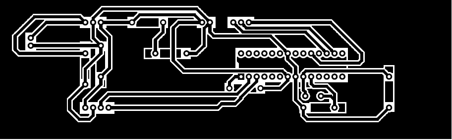
PCB LAYOUT OF MOTHERBOARD
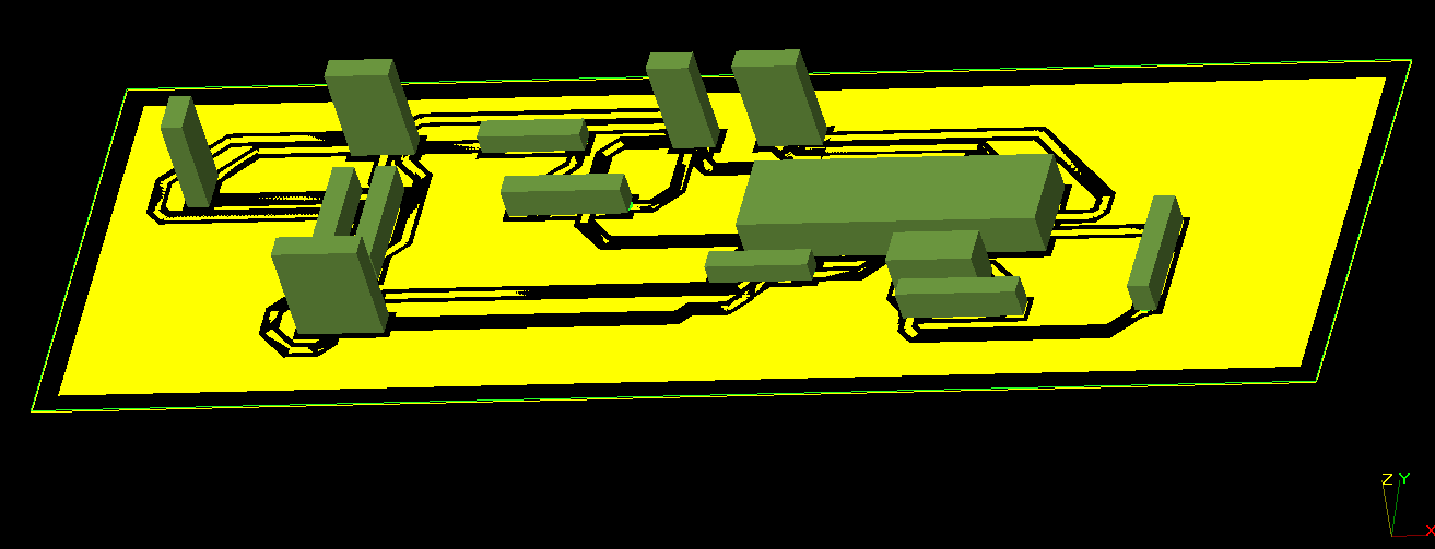
3D VIEW OF MOTHERBOARD
Motherboard is mainly consist with three circuits.
- Microcontroller circuit
- Max232 connector
- 12V to 5V converter circuit
Microcontroller
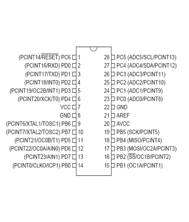
AT MEGA 328 PIN DIAGRAM
AT Mega 328 microcontroller is used for motherboard. AT mega 328 microcontroller has capture , compare, PWM ( pulse width modulation) ,ADC ( analogue to digital converter) modes and etc. Though AT Mega 328 has B,C and D ports I used only B port only for this project. PB5 (SCK ) ,PB3 ( MOSI) and PB 2 (SS) pins are used only with MAX 7219 IC for the project.
MAX232 CONNECTOR
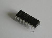
MAX 232 IC

MAX 232 PIN DIAGRAM
The MAX 232 is an integrated circuit which is compitable with RS 232 standard and consist with driver receiver. Each receiver converts TIA/EIA -232-E levels into 5V TTL/CMOS levels and each driver converts TTL/CMOS levels into TIA/EIA-232 levels. It converts RX ,TX signals from RS 232 serial port to signals suits to TTL digital logic circuits . We can give some names ,commands from computer to microcontroller using Max 232 connector. Hyperterminal software is used to send datas through the RS 232 port.
12V TO 5V CONVERTER
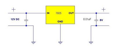
REGULATOR CIRCUIT
LED display board is connected to the mother board and LED matrix displays. One LED display board can connected to the three 8×8 LED matrix displays . Two LED display boards are used here for six 8×8 LED matrix displays
Components Of Motherboard
| Component | Quantity |
| AT Mega328 microcontroller | 1 |
| Max232 | 1 |
| 1uf capacitor | 5 |
| 470uf capacitor | 1 |
| 0.1uf capacitor | 1 |
| 22pf capacitor | 2 |
| Red LED | 1 |
| 1kΩ resistor | 1 |
| 460Ω resistor | 1 |
| 16 MHz crystal | 1 |
| 2 connector | 2 |
| 3 connector | 1 |
| 4 connector | 1 |
LED DISPLAY BOARD
LED display board is connected to the mother board and LED matrix displays. One LED display board can connected to the three 8×8 LED matrix displays . Two LED display boards are used here for six 8×8 LED matrix displays.
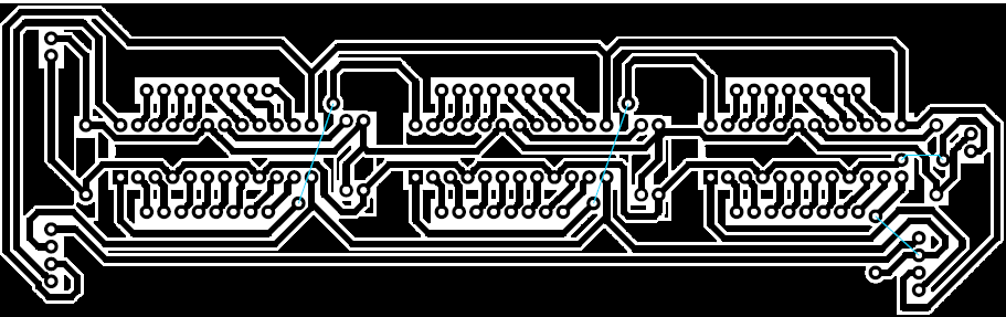
PCB LAYOUT OF LED DISPLAY BOARD
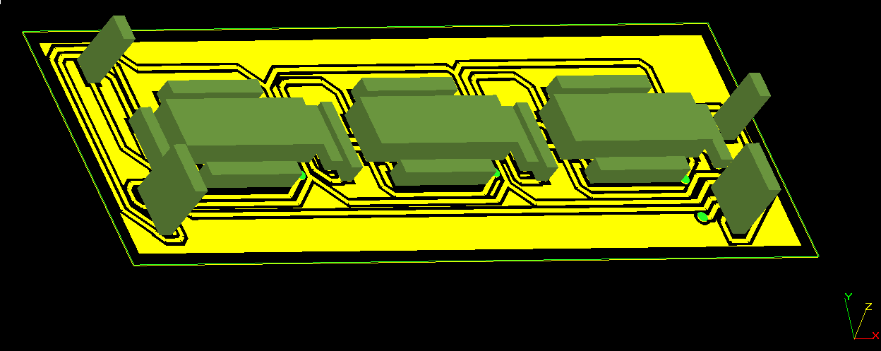
3D VIEW OF LED DISPLAY BOARD
MAX 7219
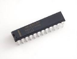
Three MAX 7219 ICs were used in LED display board. MAX 7219 and MAX 7221 ICs are used for the SPI communication. There are 24 pins in MAX 7219 IC.
DIG 0 to DIG 7 pins were connected with rows of the LED matrix and SEG DP,SEG A to SEG G pins were connected with columns of the LED matrix. Following figure shows how the three MAX 7219 ICs connected to each other with microcontroller and LED matrix displays. CLK pin and the LOAD pin of microcontroller were connected parallel to the MAX 7219. MOSI pin of the microcontroller was connected to the DIN pin of the first MAX 7219. Every DOUT pins were connected to DIN pins of other MAX 7219 ICs. Therefore data were shifted one by one.
CONNECTION BETWEEN MICROCONTROLLER , MAX 7219 IC S AND LED MATRICES
Components Of LED Display Board
| Component | Quantity |
| 8×8 LED matrix displays | 6 |
| Max 7219 IC | 6 |
| IC base | 6 |
| 8 connectors | 12 |
| 4 connectors | 4 |
| 2 connectors | 4 |
| 8 way wires | 12 |
| 0.1uf capacitors | 6 |
| 10 K resistors | 6 |
RESULTS AND ANALYSIS
Notice board can display any kind of dynamic and static message by programming again. The notice can display six letter message when static message is being showed. All parts are worked well in the device but RS 232 port is not worked. Therefore usbasp programmer is used to program the microcontroller.
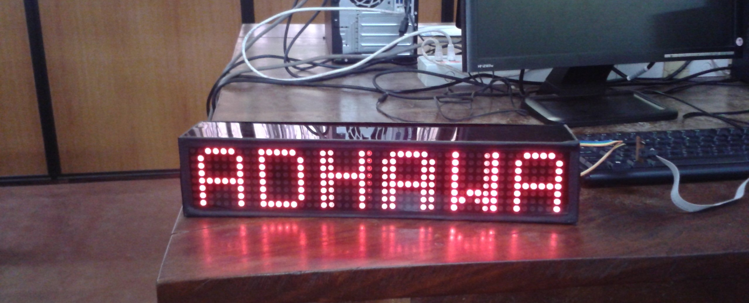
DISPLAYING CHARACTERS
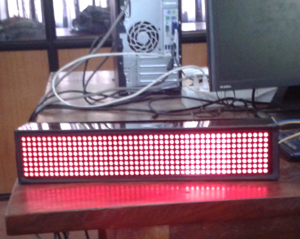
LIGHTING ALL LEDS
REFERENCES
https://sites.google.com/site/qeewiki/books/avr-guide/spi
http://awawa.hariko.com/avr_spi_hc595_en.html
https://www.mikroe.com/forum/viewtopic.php?f=13&t=24124
http://www.ee.mut.ac.th/datasheet/doc/MAX7219.pdf
https://sites.google.com/a/sci.cmb.ac.lk/esl/mini-projects/2012/spi-based-led-display-unit
APPENDIX : SCHEMATIC DIAGRAMS
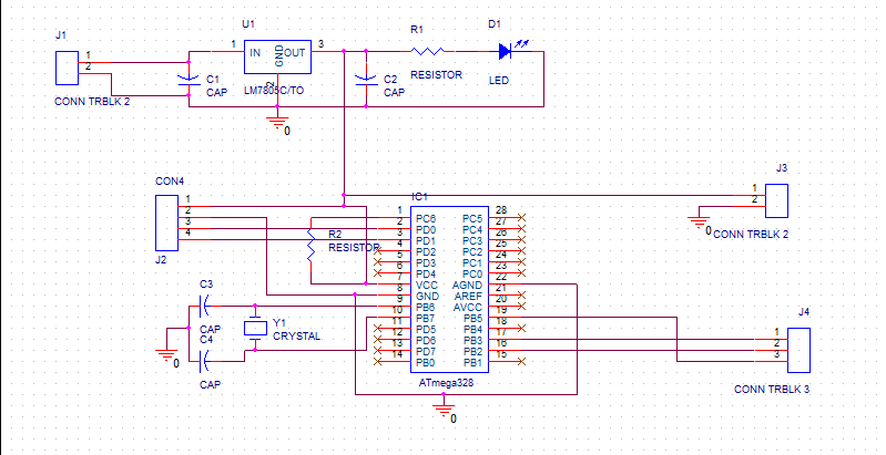
SCHEMATIC DIAGRAM OF MOTHERBOARD
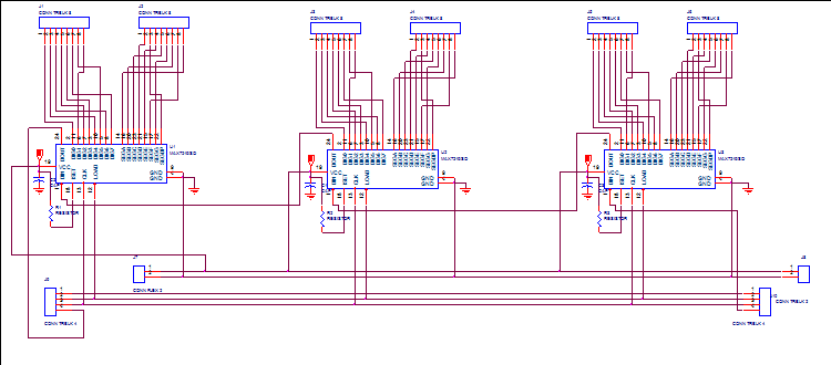
SCHEMATIC DIAGRAM OF LED DISPLAY BOARD