Introduction
Overview
Relative humidity and temperature are essential components of a comfortable working environment. However, there can be some conflict between the needs of people and the requirements for the care of collections. Other thing is that the sensor is very small and it can measure the temperature and relative humidity anyplace (e.g. Internal temperature of computer) and this instrument can be used, when doing experiment in chemistry to get temperature and humidity. Therefor the device is very useful environment condition meter.
Description
The project depends on temperature and humidity sensor and microcontroller(Atmega 328p). sensor is conducted by digital input signal and It is given output as digital signal too.So it easy to deal with microcontroller. Then two pins of microcontroller are used to controlled the sensor, one is used to give clock pulse and another one either used to give a input or to obtain a output.
The main targets faced in this project were creating the IC programming code which communicate with sensor and Microcontroller. Then correct timing and command want to active for the sensor. Other thing is how send and store the data. Then used RS232 and software for it.
Materials and methods
Material
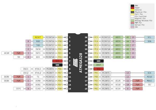
a.Microcontroller
The microcontroller is the most important part of the system and its controlling SHT75 is of relative humidity and temperature sensor, LCD display, and SD card data logger.
 Features,
- High Performance, Low Power 8-Bit Microcontroller
- 23 Programmable I/O Lines
- 32 x 8 General Purpose Working Registers
- Write/Erase Cycles: 10,000 Flash/100,000 EEPROM
- Programmable Serial USART
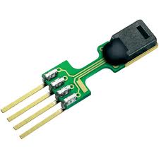
b. Humidity and Temperature Sensor IC (SHT75)
 Features,
- Energy consumption: 80uW (at 12bit, 3V, 1 measurement / s)
- RH operating range: 0 – 100% RH
- T operating range: -40 – +125°C (-40 – +257°F
- RH response time: 8 sec (tau63%)
- Output: digital (2-wire interface)
Easy replaceable relative humidity sensor for high-precision measurements.
SHT75 digital humidity and temperature sensor is the high-quality version of the pin-type humidity sensor series with cutting edge accuracy. The capacitive humidity sensor SHT75 is fully calibrated and provides a digital output. Every humidity sensor is tested upon quality and accuracy compliance. Certificate of conformance on batch level is available on request.
SHT75 IC is relative humidity and temperature sensors with pins. The sensors integrate sensor elements plus signal processing in compact format and provide a fully calibrated digital output. A unique capacitive sensor element is used for measuring relative humidity while temperature is measured by a band-gap sensor.
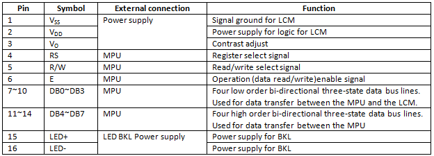
c. LCD Display (QCI1602A)
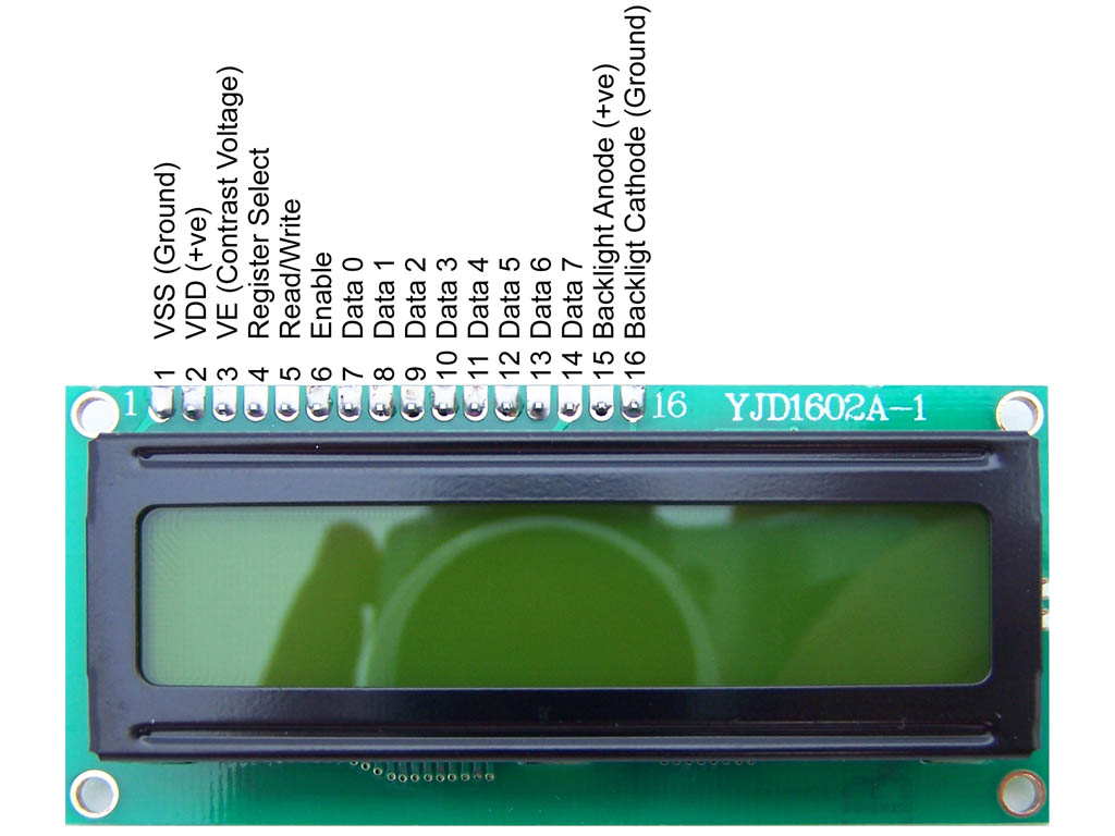
The LCD interaction is pretty simple. For the LCD to receive data it must be enabled (see picture, E pin), for it to process the command we have to disable it. So basically the LCD needs to be storing to process commands.
Using the RW and RS pin we tell the LCD we need to read or write data and if the data is a command or a piece of data (character)
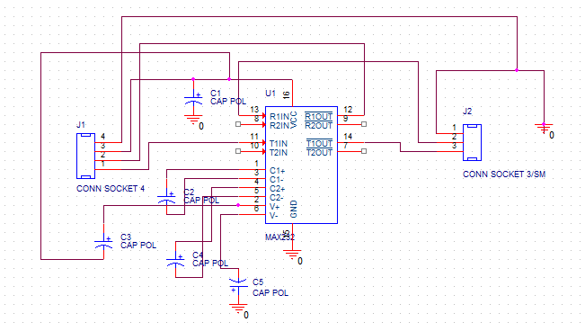
d. Max 232 IC
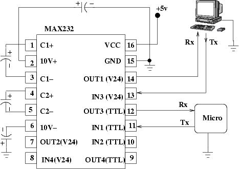
The MAX232 is an integrated circuit, first created by Maxim Integrated Products, that converts signals from an RS-232 serial port to signals suitable for use in TTL compatible digital logic circuits. The MAX232 is a dual driver/receiver and typically converts the RX,
TX, CTS and RTS signals.
f. RS-232 serial port
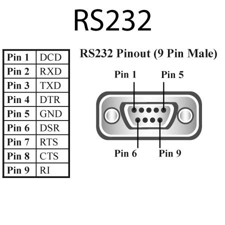
An RS-232 serial port was once a standard feature of a personal computer, used for connections to modems, printers, mice, data storage, uninterrupted power supplies, and other peripheral devices. However, the low transmission speed, large voltage swing, and large standard connectors motivated development of the Universal Serial Bus, which has displaced RS-232 from most of its peripheral interface roles.
Methodology
Communication with Sensor
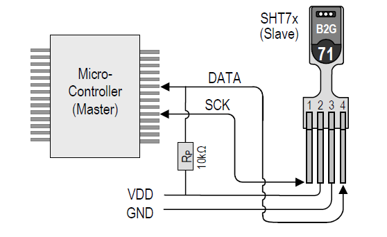
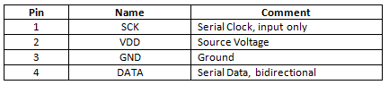
a. Serial clock input (SCK)
SCK was used to synchronize the communication between microcontroller and SHT7x. Since the interface consists of fully static logic there is no minimum SCK frequency.
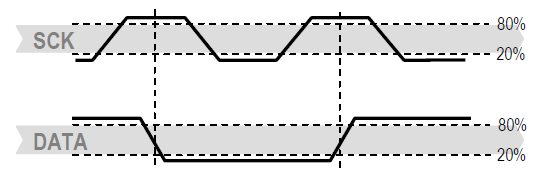
b. Serial data (DATA)
The DATA tri-state pin was used to transfer data in and out of the sensor. For send a command to the sensor, DATA was valid on the rising edge of the serial clock (SCK) and must remain stable while SCK is high. After the falling edge of SCK the DATA value been changed.
Start up Sensor
As a first step the sensor was powered up to chosen supply voltage VDD. The slew rate during power up should not fall below 1V/ms. after power-up; the sensor needed 11ms to get to Sleep State. No commands send before that time.
Sending a Command
To initiate a transmission, a Transmission Start sequence had to issue. It consists of a lowering of the DATA line while SCK is high, followed by a low pulse on SCK and raising DATA again while SCK is still high.
Measurement of RH and T
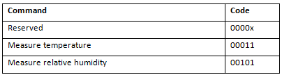
After issued measurement command (‘00000101’ for relative humidity, ‘00000011’ for temperature) the controller has to wait for the measurement to complete. That took maximum of 20/80/320 ms for an 8/12/14bitmeasurement. The time varies with the speed of the internal oscillator and can be lower by up to 30%. To signal the completion of a measurement, the SHT75 pulls data line low and enters Idle Mode. The controller must wait for this Data Ready signal before restarting SCK to readout the data. Measurement data was stored until readout, therefore the controller can continue with other tasks and readout at its convenience.
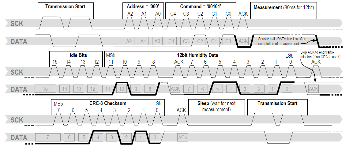
The subsequent command consists of three address bits (only ‘000’ is supported) and five command bits. TheSHT7x indicates the proper reception of a command by pulling the DATA pin low (ACK bit) after the falling edge of the 8th SCK clock. The DATA line is released (and goes high) after the falling edge of the 9th SCK clock.
Example: RH measurement sequence for value “0000’0100“0011’0001” = 1073 = 35.50%RH (without temperature compensation). DATA valid times are given and referenced in boxes on DATA line. Bold DATA lines are controlled by sensor while plain lines are controlled by the micro-controller
Calculate the values
a. Relative Humidity
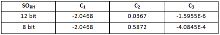
Convert the humidity readout (SORH) with the following formula with coefficients given in Table
RH LINEAR=C1+C2.SORH + C3.SORH2 (%RH)
RH LINEAR– Related humidity
SORH– numbers of pulse for RH values.
C1, C2, C3- constant values
a. Temperature
The band-gap PTAT (Proportional To Absolute Temperature) temperature sensor is very linear by design.
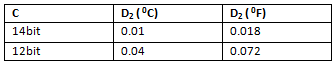
Use the following formula to convert digital readout (SOT)to temperature value, with coefficients given in Table
T=d1 + d2. SOT
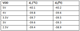
T- Temperature
SOT – number of pules
D1, D2, d1, d2 – constant values
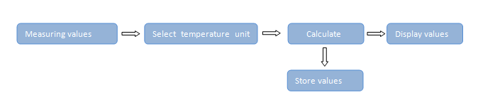
Show measuring values
Temperature is displayed either in 0F or in 0C and also Relative Humidity displayed as a percentage.The LED bulb color change with measuring unit(default 0C -green color and 0F-orange color )
The LCD display used for show to values. The output values of temperature and Relative humidity send to LCD display. The LCD displaying values of array .there for firstly made up symbols array for LCD.
Store values
USART stands for “Universal Synchronous Asynchronous Receiver and Transmitter”.
It is a mode of communication between devices which is serial in nature, i.e. data units, say a byte is transmitted one bit at a time. This is unlike parallel modes of transmission where entire data unit, say a byte (8 bits) is transmitted at once.
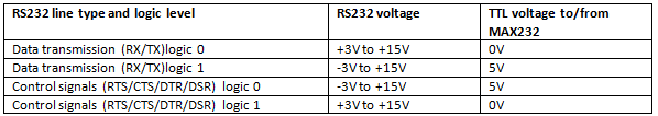
There are two data lines, RX and TX, which stand for receiver and transmitter, relative to a device. In normal microcontroller circuits the TTL (Transistor-Transistor Logic) standard for serial communication is used, where High = +5V, Low = 0V. Computers use RS232 communication standard,. This conversion is achieved through a MAX232 integrated circuit.
The communication data store in computer by the RS232, and it’s communication standard software (e.g;lookRS232-download link:http://look-rs232.findmysoft.com/download/#). The software gets the output values of temperature, relative humidity. The values store as a”*.txt” filein computer.
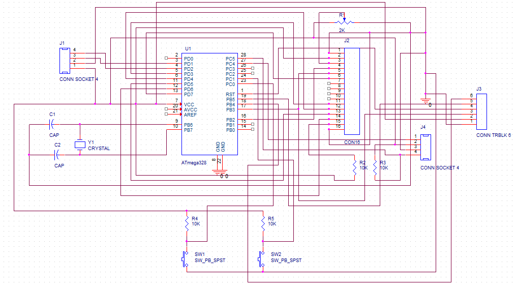
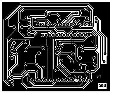
Design and construction
Firstly find out how the sensor work with AVR microcontroller, for programming and analyzed output values and it was displayed on LCD display. After find how data saved for use. Then complete schematic diagrams of the hardware were drawn. Then components were supplied and they were checked using the bread board and avr programmer. Then checked the data load with RS232 and its terminal software after coding and AVR programmer used to programming and check the circuit. Orcad 9.2 software was used to design the all the hardware parts of this project.
Low level design
Fahrenheit or Celsius unit could use to calculate the temperature. Push button was used to select preference temperature unit. Celsius unit was used as default temperature measuring unit. Few second was taken to calculate temperature value. In that period, LCD screen is displayed“Please wait….” and end of the period sensor around temperature and related humidity were showed on LED screen. Those values were transferred to computer across by RS232 serial port. And then that data was stored in computer by reliable software.Then after humidity valuewas displayed on the LCD.
High level design
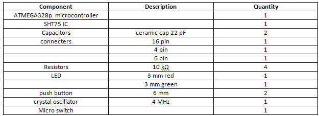
Motherboard
Components
Motherboard
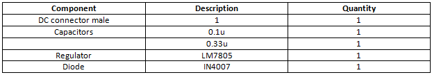
Power supply (12V convert to 5V)
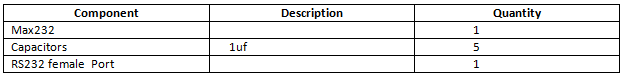
Data communicator
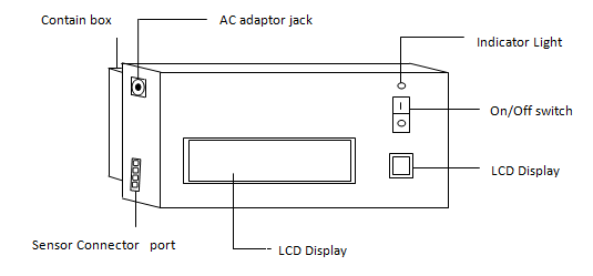
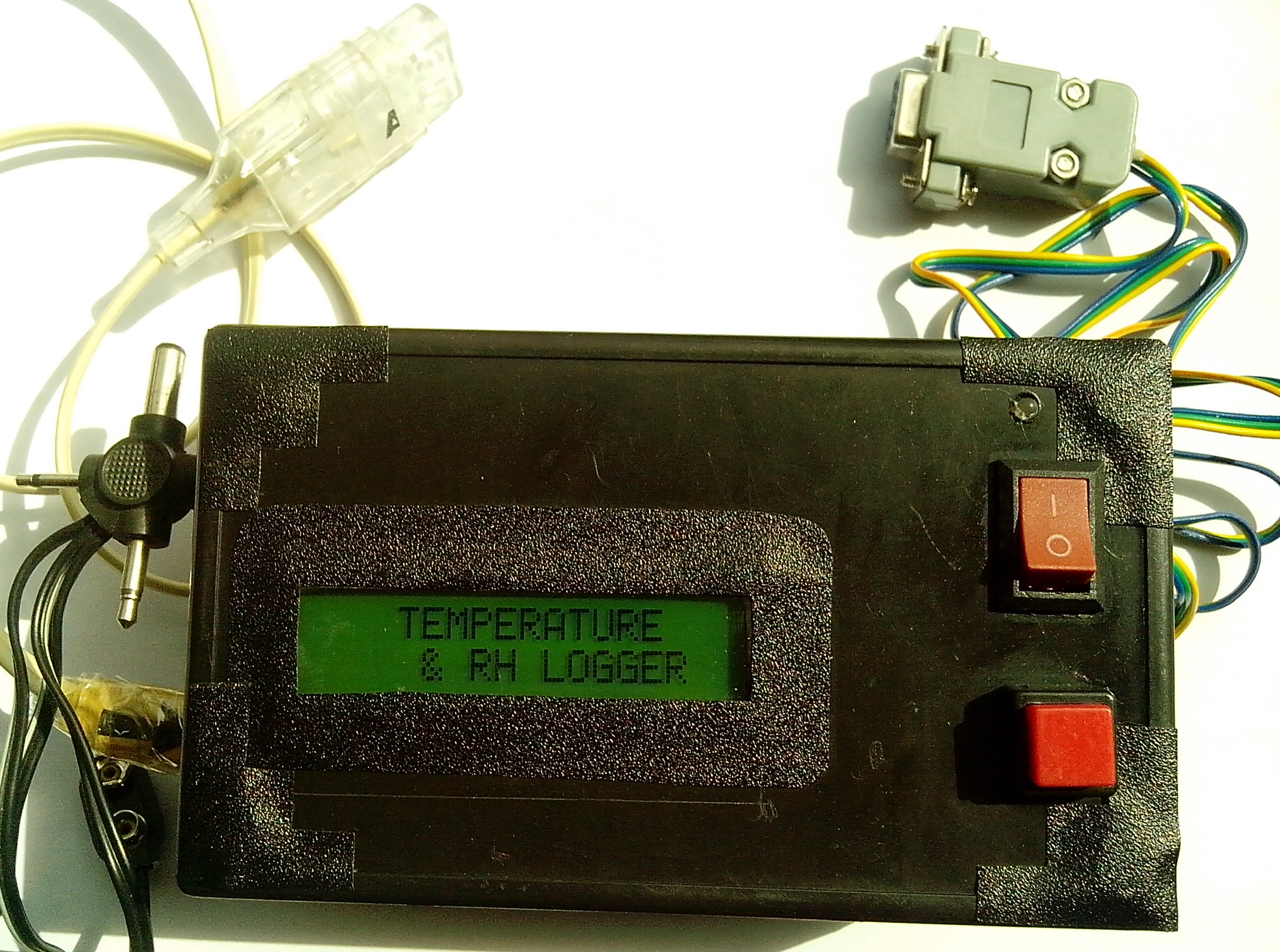
Final product
Reference
http://hekilledmywire.wordpress.com/2011/01/05/using-the-usartserial-tutorial-part-2/
http://www.atmel.com/Images/doc8161.pdf
http://robotix.in/tutorials/category/avr/usart
Appendix