Introduction
Conventional methods of displaying images or massage to public are using LCD display and dot-matrix LED displays. Propeller LED display is a special kind of device that project an image, text or time as if the images are floating in the air. Actually the floating images emerge by synchronizing LED’S blink to form an image at particular time and rate.
There are 2 main types of rotating displays, cylindrical shaped and disk shaped. Cylindrical displays are only having capable of displaying text and digits and disk shaped displays have the ability to display analog clock. This project is a cylindrical type digital propeller clock with help of some mechanical assembly, LED count and hardware requirement.
Propeller Clock is a clock, displayed by a mechanically rotating bar of Light Emitting Diodes (LED s). In the display, the LED s are not illuminated constantly. The LED s turn on and off at precise intervals, one after another, extremely rapidly while being rotated with several thousands of rounds per minute (RPM). Human eye is an integrating optical sensor that has about 0.1 s integration time. Hence, the human eye, registers an image as an integral of photons reached to the eye about 0.1 s time. This phenomena is known as Persistence of Vision (POV) that gives the illusion of a static stable display. POV of human eye has been used as the basic principle in this project.
Materials and Methods
Microcontroller
The most important part of the system is microcontroller. It controls whole system. In here I have used an ATmega32A microcontroller.
ATmega32A has an 8-Bit Processor and it has 32K of program space, 32 I/O peripherals. It runs up to 16MHz with external crystal.
The pin diagram of the ATmega32A microcontroller given below in Figure 1,

Figure 1: Pin Diagram of ATmega32A
Motor
All types of motors used to convert electrical energy into mechanical energy. Motors can be found in VCR’s, CD players, toys, robots, fans, etc. The motor performance is very important in circuit design. This is because the electrics motors directly affect its speed and pushing capability.
Repeated scanning of the display is necessary for continuous vision of image. This task is achieved using continuous circular rotation of the whole circuit assembly. Therefore a DC motor has used as the prime mover.
DC motors looks quite simple. When applying a voltage to both terminals, it will spin. DC motors are non-polarized motors. Which means when changing the voltage direction, the motor will rotate in both directions, forward and backward. Most of typical dc motors are rated from about 5V-12V. The larger motors are often 24V or more. But for the purpose of this project, it is necessary to use 6V-12V range motor and therefore a 6V-9V range motor is used. Voltage is directly related to torque of the motor. When increasing the supply voltage, the higher torque will be produce. And the more current supplied, the higher rpm (revolutions per minute) will be produce. Most of DC motors has low torque and high rpm.
Led Module
LED module consisting of 10 bright red color LEDs and it is fixed in corner of the arm of the propeller. It is a main part of the circuit. LED module is used to displaying the characters and symbols. These 10 LEDs are connected with each pins of the port A and two pins of the port B of microcontroller.
Phototransistor
In order to know when the system should restart displaying the current image or massage on the propeller clock, we need a known reference point called home point. A phototransistor and an IR LED are used to determine that reference point. An IR LED shines bright into a phototransistor, it cause to turns the transistor ‘On’ condition with connecting the +5v collector pin to the +0v Emitter pin. The microcontroller will see this as falling edge transition and know right away its back at the home location after 360°. Figure 2 shows how to interface a phototransistor to the microcontroller.
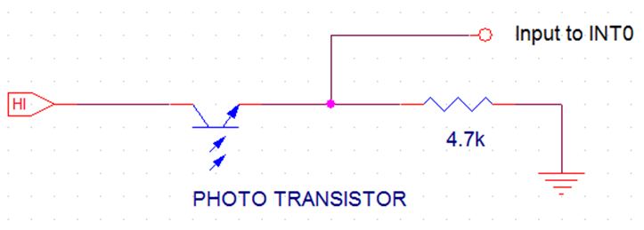
Figure 2: Interfacing the phototransistor to the microcontroller
IR LED
An Infrared LED (IR), also known as Infrared transmitter, is a special purpose LED that transmits infrared rays with nanometer range of wavelength. IR transmitters along with IR receivers are commonly used as sensors. The appearance is same as a most common LEDs.
Since the phototransistor is only triggered by the IR radiation, an IR LED must be placed nearby. The intensity of the IR radiation determines how much current is generated in the photo transistor. Therefore a large current must flow through the LED to create a higher intensity. Figure 3 shows an IR LED circuit.
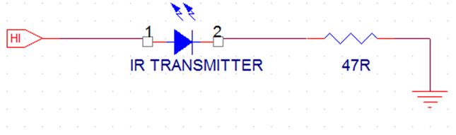
Figure 3: IR LED circuit
METHODS
POV (Persistence of Vision)
This is the phenomenon which is related to vision capability of human eye by which an after- image is thought to persist for approximately one sixteenth of a second.
So, if someone is observing the images at least 16 frames per second, then they appear to be continuous. For example, if we want to display ‘1’, then the series of lighting up of LED s would be like bellow.
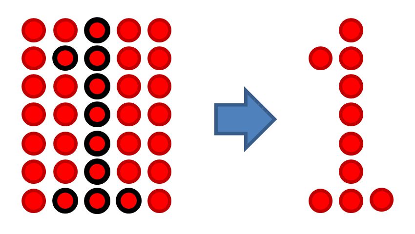
Figure 4: Display a number using column of 7 LED s
Speed of LED s (Frame Rate)
The rotational speed of the LEDs is directly affects to the frames per second. If there is a more frame rate, it cause to the less flickering of the picture. It is not easy to achieve high frame rates in this project because of the propeller display displayed the picture mechanically. The propeller has to be very well balanced to reduce vibrations and keep proper speed of the rotating LEDs.
Here is a calculation for calculate the rotation speed of the LEDs when a picture is displayed with a frame rate of 25Hz.
f = 25Hz (Frame rate)
r = 7cm (Radius from center of rotation to the LED’s)
c=2 * r * 3.141=2 * 0.07m * 3.141=0.43974m (circumference)
v= f *c * 3600=25 * 0.43974m * 3600 = 39576.6m/h
=39.5766 km/h.
According to above calculations, it can be interpret the radius is proportional to the rotation speed of LED s.
Interrupts
In short, an interrupt is a way for an external (or, sometimes, internal) event to pause the current processor’s activity, so that it can complete a brief task before resuming execution where it left off.
There are two external interrupts in ATmega32A named INT0 and INT1.These INT0 and INT1 external interrupts can be triggered by a falling or rising edge or a low level. Here we use external interrupt 0 (INT0).
Mechanical Assembly
Mechanical assembly plays a main role in proper functioning of this project. The display is displays the time by rotating the whole assembly in a circular path.
Following Figure 5 shows the most reliable way of create mechanical assembly that we used.
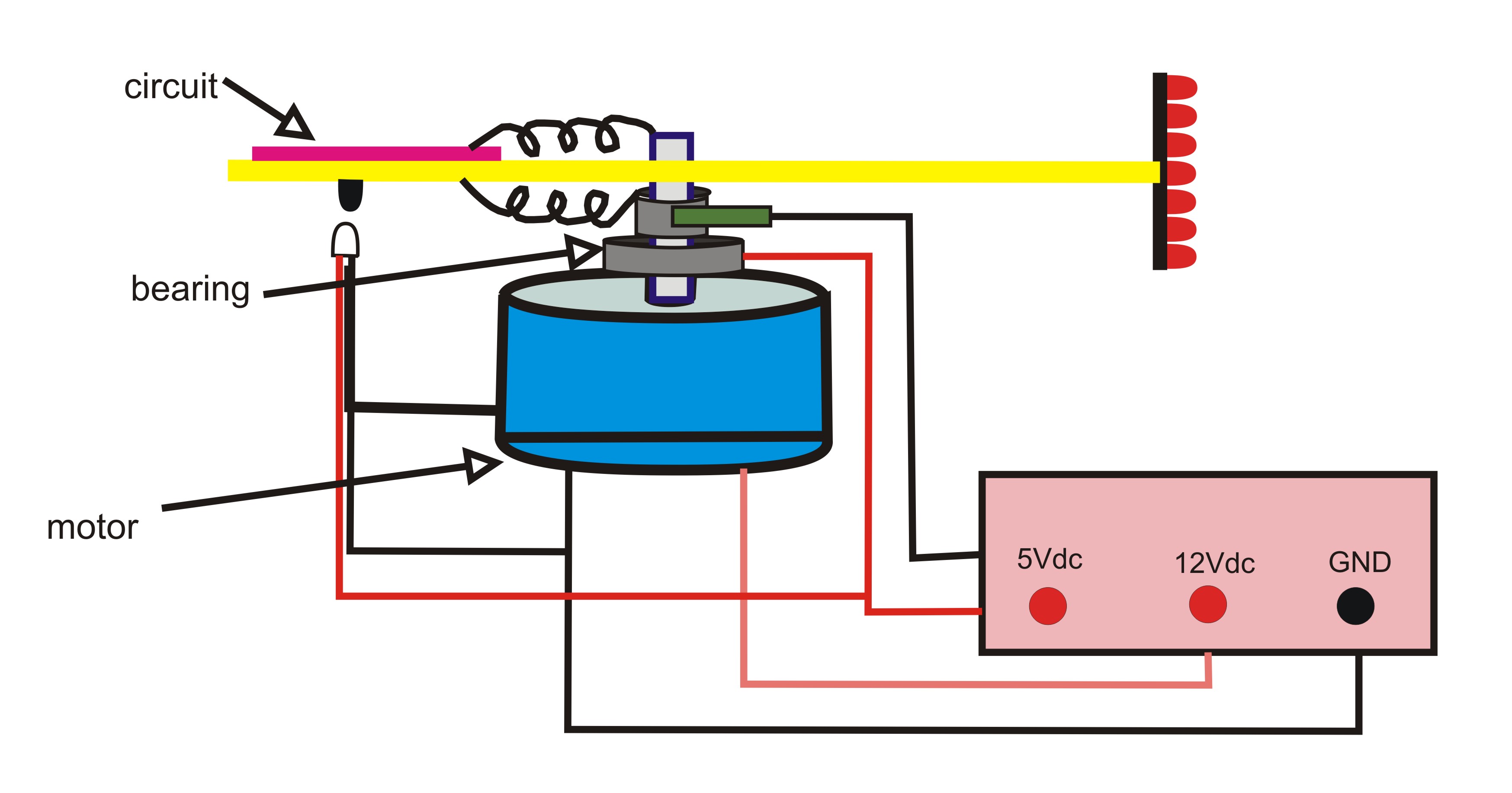
Figure 5: Mechanical Assembly
Here a major challenge that we faced is the connecting +5V supply to the rotating circuit. We tried the various methods to do that. But finally we choose a method, as shown in the above figure.
As seen in above diagram, one supply terminal (Vcc) is provided through a baller bearing. Other supply terminal (GND) is connected by using cylindrical disc-brush arrangement which was design by me. The current can be supplied using that, because of the brush keeps its contact with the cylindrical disc.
Design and construction
Mother Board
This motherboard contains the ATmega32A microcontroller and all other requirements to get it in to working condition. Also this contains a programing port which allows programming the microcontroller using USB programmer. PORTA and some pins of POARTB are connected to LED panel and POARTC is used to connect push buttons. The wire outs for the daughter board were left through 12-pin connector. Figure 6 and Figure 7 shows the PCB layout designs of motherboard and the list of components are found in the Appendix C
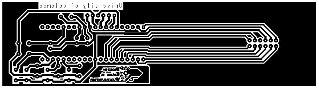
Figure 6: Mother Board PCB Layout
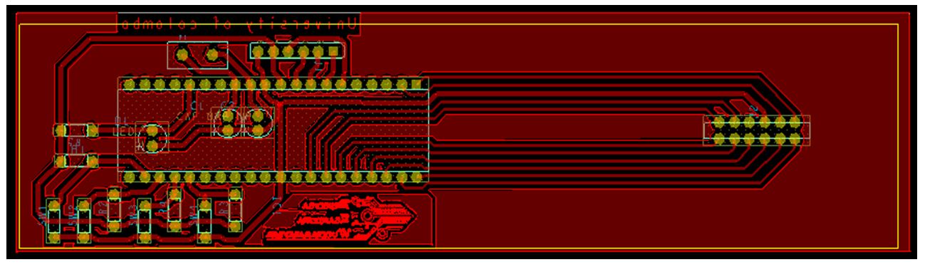
Figure 7: Mother Board PCB Layout with Components
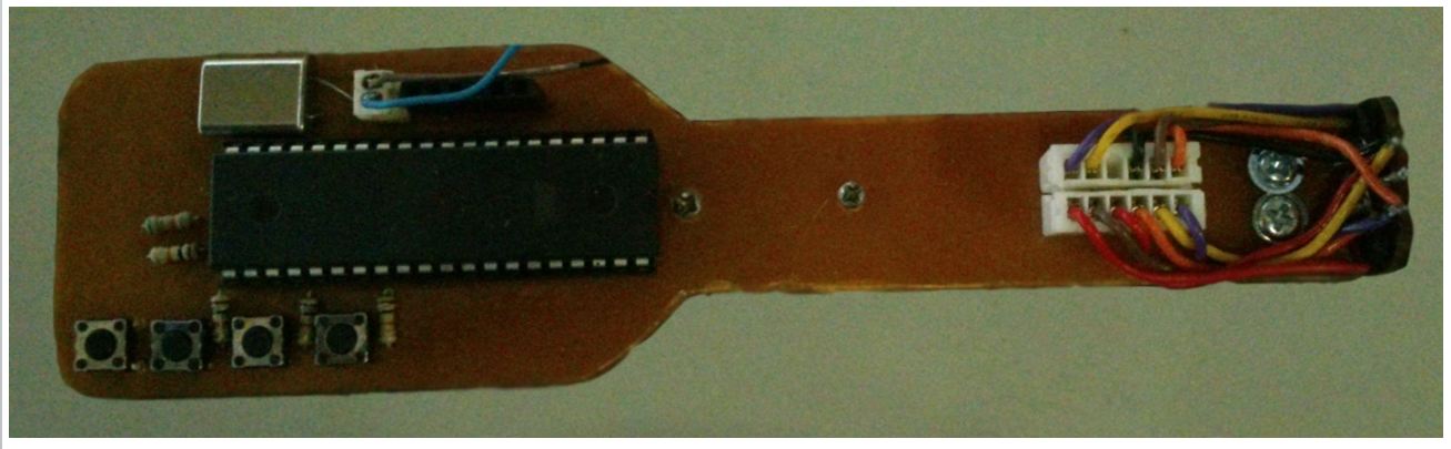
Figure 8: Complete Mother Board
Daughter Card
The LED panel was mounted to motherboard as a separate module. Figure 9 shows the PCB layout of the daughter card and the list of components are found in the Appendix C.

Figure 9: Daughter Card PCB Layout with Components
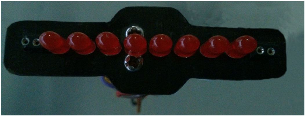
Figure 10: Complete Daughter Card
Voltage and Current Limitations
5 V DC voltage provided to Mother board using 5 V regulator circuit. Mother board will provide the input voltage to Daughter board. 500 mA current supply provided to mother board to get all components to a perfect working condition.
9 V DC voltage provided to Mother board using 9 V regulator circuit. User can plug a 9Vdc-24Vdc range DC power supply as the power source of Motor. Minimum 500mA and Maximum 1000 mA current supply must provide to Motor to get a proper rotation speed.
ATmega32A microcontroller
Input voltage = +2.7 V to +5.5 V
Current = 200 mA (max)
DC Motor
Input voltage = 3 V to 9 V
Current = 1000 mA (max)
Software Design
The software for the device is rather simple. LED panel lines connected to PORTA0- PORTA7, PORTB1, and PORTB2 pin. PORTC0-PORTC3 pins connected to push buttons and photo diode is connected to INT0 pin. The basic idea of the software design is, it should run a real time clock and when the interrupt routine is executed, it should read the time and should display that time on LED display with help of the binary conversion. Also when user increases the time manually, the program should increase the minute, hours and clock display type (12h or 24h) separately.
Results
The System was able to display the time with digital type on the rotated LED display and system can display seconds, minutes and hours separated with ‘:’ sign.
User can do the time adjustment by pressing push buttons. There are 4 push buttons on motherboard. 3 push buttons are reserved for the time adjustments. “Minute” button is reserved for increase minutes and “Second” button is reserved for increase seconds. “12h/24h” button is reserved for select the display mode. User can select the display mode of time as 12hours clock type or 24 hours type by pressing this button. If user select 12hours clock type, he/she can only increase the hours until 12 reached. After 12 it reset to 0. As well as If user select 24hours clock type, he/she can only increase the hours until 24 reached. After 24 it reset to 0.
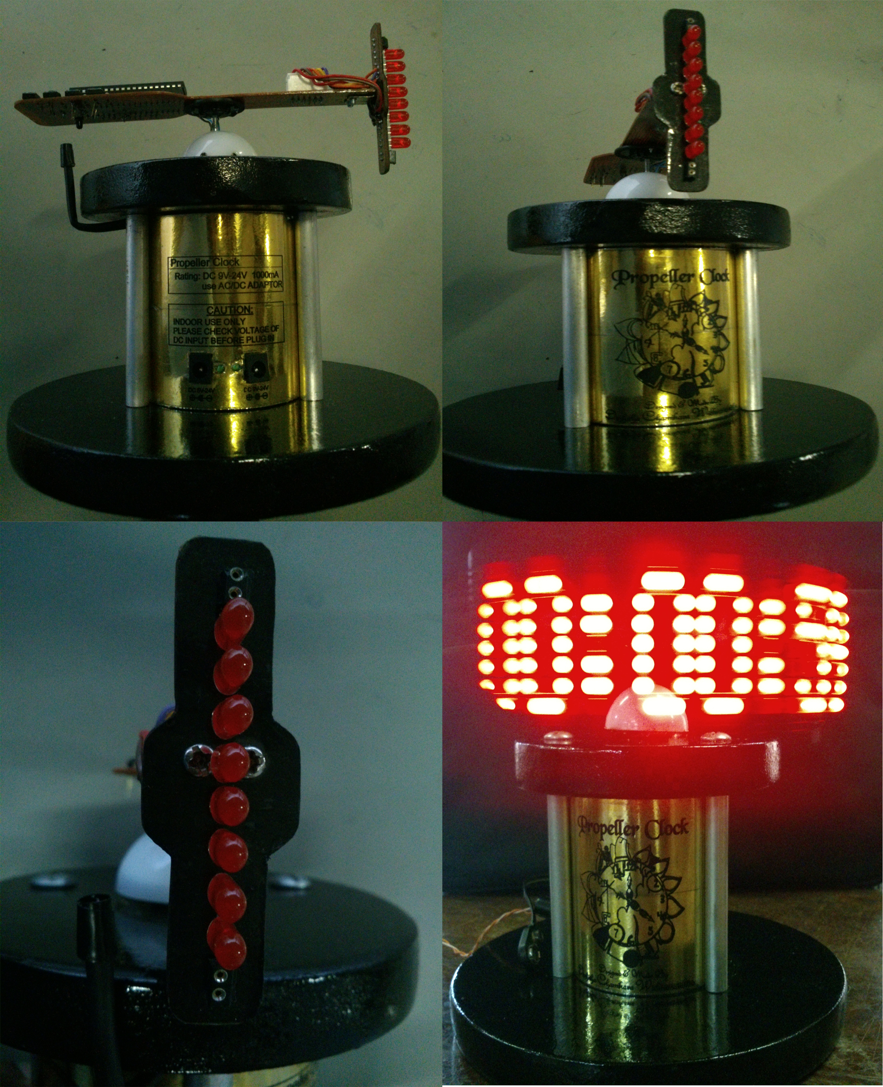
Figure 11-Final device
Conclusion
The propeller should build as lighter and more stable. It matters to a faster rotation of propeller. And if the assembly is balanced perfect with having good mechanical strength, then it can achieve stability, and rotate at high RPM. More clear display can get using bright light LED s. An IR transmitter receiver pair should be used to get a ‘home’ point for the propeller clock. It is used to detect the completion of one revolution.This will improve the overall efficiency of this display and this gives a clear picture without flicker.
Limitations
This devise is a cylindrical type display with only having capable of displaying text and digits. To display analog clock, we must create disk shaped propeller display.
Improvements, Future Enhancements for the Device
- There are many ways to enhance this devise with many other added features. Or it could also be used for some other project as a basic component.
- This devise displays only the time. Therefore we can modify this devise for display date besides time.
- User only can do the time adjustment when propeller is at the rest of condition. Therefore a remote system can be used to set time and date.
- This devise can be modifying as a computer based display board. A wireless system can be used to communicate between the PC and the device. This would let the user to display any massage easily on propeller display.
- LED patterns can be display using this devise. We have to modify the program for LED patterns.
- We can use an external Real Time Clock (RTC) module as the clock. It gives time and date with 100% accuracy.
References
http://www.atmel.com/Images/doc8155.pdf
http://www.luberth.com/help/propeller_clocks_backups/sylvain_bissonnette/
http://homemaderobo.blogspot.com/2012/03/propellerrotating-led-display.html#comment-form
http://en.wikipedia.org/wiki/Persistence_of_vision
http://petemills.blogspot.com/2011/05/real-time-clock-part-1.html
Appendix A – Hardware Schematics
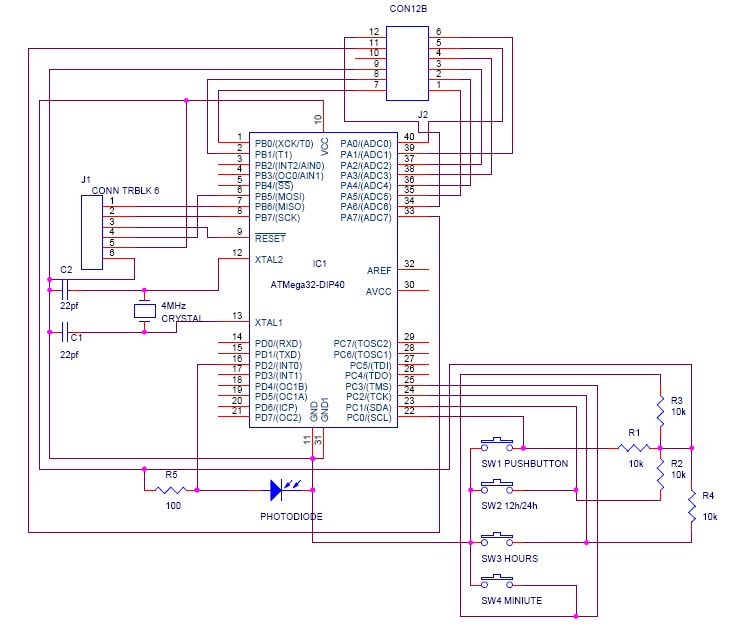
Figure 12-Motherboard schematic diagram
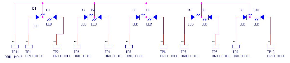
Figure 13-Daughter card schematic diagram
Appendix B – Code Listing
Appendix C – Component Lists
Table 1: Mother Board Component List
| COMPONENT | QUANTITY |
| ATmega32A Microcontroller | 1 |
| 10k | 4 |
| 68k | 1 |
| 2pf | 2 |
| 4MHz Crystal | 1 |
| Photo Diode | 1 |
| 40 Pin IC Base | 1 |
| Push Buttons | 4 |
| 6-Pin Female Socket | 1 |
| 12-way wire connector | 1 |
Table 2-Daughter Card Component List
| COMPONENT | QUANTITY |
| Red LED | 8 |
| White LED | 2 |
| 12- Way Wire Connector | 1 |