Introduction
The line following car is a car that follows a black line on white surface. The idea to make a line following car is inspired when I saw some video clips of line following cars. The basic concept of the line following car is that the line is detected using optical sensors and according to the signal recieved from the sensors, microcontroller decides what movement should follow the car.
High level design
This line following car uses phototransistors that out puts a analog signal according to the light intensity fall on it. Here black surface absorbs light more than the white surface, this is the basic theory of detecting the black line. The states of the photo transitors captured by the comparator and it produce 1 or 0 for the recieving signal. According to the signals recieved by microcontroller(PIC16F877A) is controlled the car. For moving the car it is used the differential steering method so when car try to turn around some point the nearest motor is slow down the speed or if it moves in straight motors speeds are same. If the car detects small deviation from the path the car will turn to left or right to center the car on the black line. If the car deviates more from the line it will get turn drastically.
Hardware
To built the car I collect two wheels with motors from a toy and it is fixed to a plastic board and one caster wheel find from a waste table. The sensor circuit is consists of four photo transitors and ir leds. The four sensors fixed to make a straight line and each sensor seperate from a distance of 1.5 cm. Sensor unit is fixed infront of the car so that the distance between sensors and the floor is less than 1.5 cm. Also the sensor cicuit is fixed so that it can be adjust the distance with the floor. A comparator (lm324) is used to compare the signals recieved from the sensors since the microcontroller deals with digital values. That will send logic one or zero to the microcontroller. A l293D motor driver is used to drive the two mortors. Line following car needs to use a motor driver since motors consume high current. Motor driver is enable by two PWM signals that was generated by software. Since PIC16F877A can generate only one PWM signal at some instance it needs to use a software generated PWM. The main board that consists of microcontrller, motor driver and comparator are mounted on the car.
Images
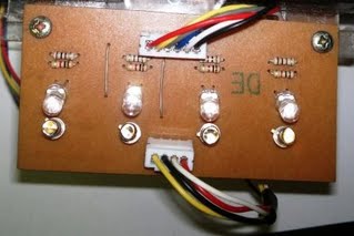
Sensor Circuit
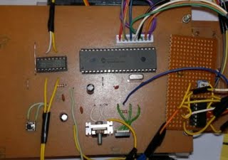
Main Circuit
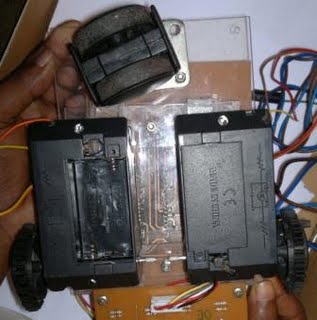
Car Chassis
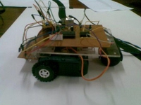
Completed Device
Power
To supply the 5v to the circuit I used a 7805. A motor driver is powered using another power line separate from the main power line. I used external power sources by using wires to supply the power for this car.
car chassis completed device
Software
Algorithm of the follwer
x 1 1 x – move forward with maximum speed
1 x x x – turn right and move forward
x x x 1 – turn left and move forward
x 1 0 x – turn right and move forward
x 0 1 x – turn left and move forward
0 0 0 0 – reverse
here x means that don’t care whether it is 0 or 1
1 means detect the black line and 0 means detects the white surface
since the programming language and softwares are predetermined I used MPLab IDE and high-tech c to programme the microcontroller.
Results
My line follwer is followed the line as I expected but it is not totally error free. The bugs arise can be eliminated with some possible improvements.
YouTube Video
Improvements
The motors I used are not fully stable with voltage and at the initial start it need more power to start moving. So it is better to use geared motors.
It can be used more sensors than I have used here then it will achieve a higher resolution of detecting the line. This will help to follow the line more accurately.It is recomended to use a small and good caster wheel that will help the car to move smoothly.
I used two external power sources for this car but it is better to use batteries. But I noticed that should use a light chasse when using batteries and powerful motors (It can be used geared motors or stepper motors).
Apendix
Component list
| Component | Quantity | Cost in Rs.(1 quantity) |
| PIC16F877A | 1 | 400.00 |
| lm324N | 1 | 12.50 |
| l293D | 1 | 225.00 |
| ST-1KLA | 4 | 100.00 |
| IR led | 4 | 35.00 |
| 4 MHz crystal oscillator | 1 | |
| l7805 | 1 | 20.00 |
| push button | 1 | |
| variable resistor | 1 | |
| 22 pF capacitor | 1 | 1.00 |
| 100 uF capacitor | 2 |
Code listing
C code can be downloaded from attachments.
Schematic diagrams
shematic diagrams of proccessing unit and sensor unit of the line following car can be downloaded from attachments.