Introduction
The STM32 F3xx micro-controllers are based on the ARM Cortex-M4 core. This Cortex-M4 core is used by number of manufactures like Toshiba, ARM, NXP etc. Sharing same core has lot of benefits. Most important benefit is programming tools, compilers and debuggers are common for wide range of devices. Also provide opportunity to develop simple hobby like systems to more complex real time system like autopilot in air crafts.
STM32F3 is a family of microcontrollers. Depending on requirement a chip can be selected for a particular application. Chips of same family mainly differ from each other in peripherals connected to it. Therefore these chips has different memory sizes, speeds, timers, number of particular alternative function pins and ect. Another important thing is all the chips in same family shares same set of programing libraries. So knowing how to program one chip make you capable of programming them all. Also the code is portable among the chips and without a change or with simple change, the code can be reuse in another chip.
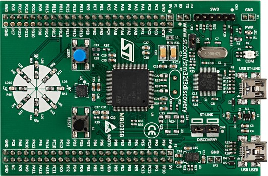
STM32F3DISCOVERY Board – http://www.st.com
Understanding the board
In this tutorial series STM32F3 Discovery board was used to demonstrate programming STM32F3xx micro-controllers. First all of understanding STM32F3 Discovery board and chip is important. These datasheets are available on http://www.st.com which is the official website of STMicroelectronics. In this particular board STM32F303VC chip is used.
Following link contains all the information regarding STM32F3 Discovery board.
http://www.st.com/web/catalog/tools/FM116/SC959/SS1532/PF254044
Following link contains full reference manual for STM32F3 series.
http://www.st.com/web/en/resource/technical/document/reference_manual/DM00043574.pdf
The above mentioned document and resource are the most important things if one start programming STM32F3
Following are the features available in STM32F3 Discovery board
- STM32F303VCT6 microcontroller featuring256 KB Flash, 48 KB RAM in an LQFP100 package
- On-board ST-LINK/V2 with selection mode switch to use the kit as a standalone ST-LINK/V2 (with SWD connector for programming and debugging)
- Board power supply: through USB bus or from an external 3 V or 5 V supply voltage
- External application power supply: 3 V and 5 V
- L3GD20, ST MEMS motion sensor, 3-axis digital output gyroscope
- LSM303DLHC, ST MEMS system-in-package featuring a 3D digital linear acceleration sensor and a 3D digital magnetic sensor
- Ten LEDs:
- LD1 (red) for 3.3 V power on
- LD2 (red/green) for USB communication
- Eight user LEDS, LD3/10 (red), LD4/9
- (blue), LD5/8 (orange) and LD6/7 (green)
- Two pushbuttons (user and reset)
- USB USER with Mini-B connector
- Extension header for all LQFP100 I/Os for quick connection to prototyping board and easy probing
- Comprehensive free software including a variety of examples, part of STM32CubeF3 package or STSW-STM32118 for legacy Standard Library usage
- STMicroelectronics (Datasheet)
Reading and Understanding Datasheet
The UM1570 (User Manual) is available in the first link mentioned above. In this section what’s on datasheet is discussed before starting setup the software and hardware. Since this is bit complex board and lot of new stuff is there to understand it is really important to have good understanding about board.
Quick start
Under this section first step of ARM programing is described.
Follow the sequence below to configure the STM32F3DISCOVERY board and launch the DISCOVER application:
- Check the jumper positions on the board, JP3 on, CN4 on (DISCOVERY selected).
- Connect the STM32F3DISCOVERY board to a PC with a USB cable type A to mini-B through the USB ST-LINK or USB USER connector to power the board. The red LEDs LD1 (PWR) and LD2 (COM) light up.
- The eight LED indicators blink sequentially.
- Press the USER button to enable the MEMS gyroscope sensor.
- Observe how the blinking of the LEDs indicates the gyroscope movements.
- Press the USER button again to enable the MEMS e-compass sensor.
- Keep the board in a horizontal position. One of the eight LEDs lights up to indicate the direction of the north.
- Tilt the board and the eight LEDs blink again
From Datasheet
Initially there is a program stored in STM32F3 board. When power is supplied as mentioned in above it runs the default program which demonstrate function of a gyroscope and a compass.
Hardware and layout
STM32F3DISCOVERY Hardware layout
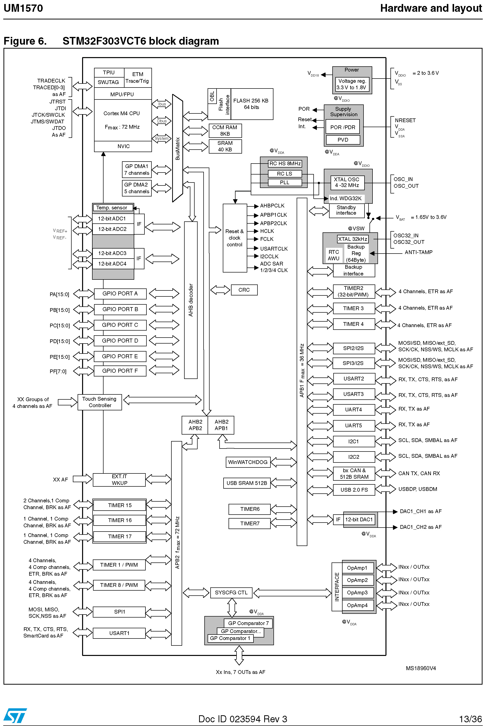
STM32F303VCT6 block diagram is one of most important diagrams in Datasheet. It shows the connectivity of each and every peripherals and sections connected to these peripherals. To write a program understanding the diagram is necessary. Let’s says one want to handle something connected to GPIOE (General Purpose Input Output E) then AHB decoder must call to handle the matter because GPIOE is connected to AHB decoder according to block diagram. These topic are discussed in details in next tutorial.
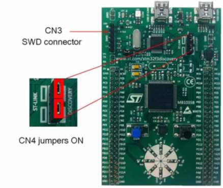
Embedded ST-LINK/V2
The ST-LINK/V2 programming and debugging tool comes with STM32F3 Discovery Board. There are two types of configuration for ST-LINK/V2 depending on jumper states.
- Program/debug the MCU on board,
- Program/debug an MCU in an external application board using a cable connected to SWD connector CN3.
| Jumper state | Description |
| Both CN4 jumpers ON | ST-LINK/V2 functions enabled for on-board programming (default) |
| Both CN4 jumpers OFF | ST-LINK/V2 functions enabled for application through external CN3 connector (SWD supported) |
Board jumper Status
Important On board component and sensors
There are several components in the board which can use for testing purposes when programming STM32F3. Therefore connections of these components are crucial to know.
LEDs
- LD1 PWR: red LED indicates that the board is powered.
- LD2 COM: LD2 default status is red. LD2 turns to green to indicate that communications are in progress between the PC and the ST-LINK/V2.
- User LD3: red LED is a user LED connected to the I/O PE9 of the STM32F303VCT6.
- User LD4: blue LED is a user LED connected to the I/O PE8 of the STM32F303VCT6.
- User LD5: orange LED is a user LED connected to the I/O PE10 of the STM32F303VCT6.
- User LD6: green LED is a user LED connected to the I/O PE15 of the STM32F303VCT6.
- User LD7: green LED is a user LED connected to the I/O PE11 of the STM32F303VCT6.
- User LD8: orange LED is a user LED connected to the I/O PE14 of the STM32F303VCT6.
- User LD9: blue LED is a user LED connected to the I/O PE12 of the STM32F303VCT6.
- User LD10: red LED is a user LED connected to the I/O PE13 of the STM32F303VCT6.
Push buttons
- B1 USER: user and wake-up button connected to the I/O PA0 of the STM32F303VCT6.
- B2 RESET: push button connected to NRST is used to RESET the STM32F303VCT6.
E-compass/accelerometer – I2C serial interface
Gyroscope MEMS (ST MEMS L3GD20) I2C/SPI serial interface
At the end of the Datasheet pins and their alternative functions are explained in details. These topics will be discussed in next tutorial when necessary.