Introduction
Kitchen timer is a device that can be used as a timer to disconnect any electrical device according to the time what the person can set as the connecting time of the electrical device. And normally it can be used for the kitchen items and that is why this device is named as “KITCHEN TIMER”.
There are various types of switching mechanisms to turn off the electrical power to an electrically connected device by manually or automatically. As far as concerned about the switching devices there are electronically controlled and mechanically controlled switches. This product KITCHEN TIMER belong to the electronically controlled automatically turn off switching mechanism which is depend on the time what it set at the initial. The advantage of having a KITCHEN TIMER is user doesn’t want to have an attention to turn off the electrical device manually but it automatically turn off the device and give an alarm to indicate the time is over.
when it connects an electrical device to the product kitchen timer, initially user has to set the time period which he wants to connect the electrical device and once it presses “OK” button and give the command to connect the electrical device to the external power source and it will automatically connect the circuit by using the Relay and starts the counting downwards the time. Once the down counting time comes to the end point which is zero, it will automatically disconnect the circuit by using the Relay and give an alarm to the person who is using the electrical device by using a Buzzer.
Materials and Methods
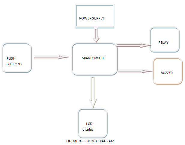
This product has only one circuit and it includes all power supply circuit, relay circuit, Buzzer circuit, LCD display and other components itself.Mainly it has LCD display to display the time and other things, pushbuttons to set the time give commands to the Atmega328 IC, Relay to connect and disconnect the circuit to external electrical device, Buzzer to give the alarm signal when it is finished the down counting time and a plug point which is connected on to the KITCHEN TIMER box to have power to the external electrical device, and power supplying circuit with a transformer to give the power to the internal circuit components and the Atmega328 IC.
-
Atmega328 Micro-controller
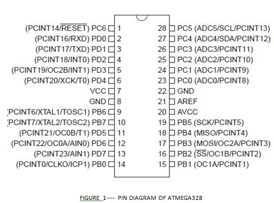
Most important item to build this product is the Atmega328 IC which has altogether 28 pins. And it has 23 I/O ports. All the counting and controlling of whole system is done by this marvelous device.
To build this product It is used PORTB 2, PORTB 3, PORTD 7, PORTD 3, PORTD 4, PORTD 5, PORTD 6, PORTD 0, PORTD 1, PORTD 2, PORTB 0, PORTB 4, and PORTB 5 to have various I/O purposes.
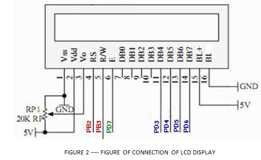
- LCD display (16×2)
In the LCD display it can have 2 rows and each row it is capable of having 16 characters. The contrast of the LCD display can be controlled by using variable resistor.
-
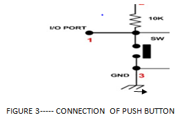
Push buttons
In this product it has used 5 numbers of push buttons for different types of duties.It is connected the Push buttons as the method when it is at not pressed (off) state it gives 5V and once it is pressed the button it connects to zero or ground.
- Resistors
In this product it is used mainly 10K resistors as pulled up resistors and 1k to relay circuit and 10k variable resistor to control the contrast of the LCD.
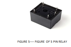
- Relay
A relay is an electrically operated switch. Current flowing through the coil of the relay creates a magnetic field which attracts a lever and changes the switch contacts.In this product Relay is used to connect and disconnect the externally connected electrical device with the controlling of the microcontroller. When it is given the signal (5v) to the relay it will automatically connect the external electrical device by connecting the path to flow AC current and when it is disconnect the signal to the relay it will automatically disconnect the electrical path via magnetic induction inside the relay.
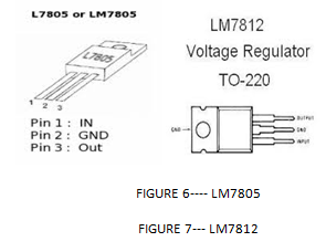
- LM7805 & LM7812
LM7805 is used to regulate the output voltage to have exactly 5V to power up the microcontroller, Buzzer and other components which need 5V input. LM7812 is used to regulate to have exactly 12V to the relay because I selected 12V relay.
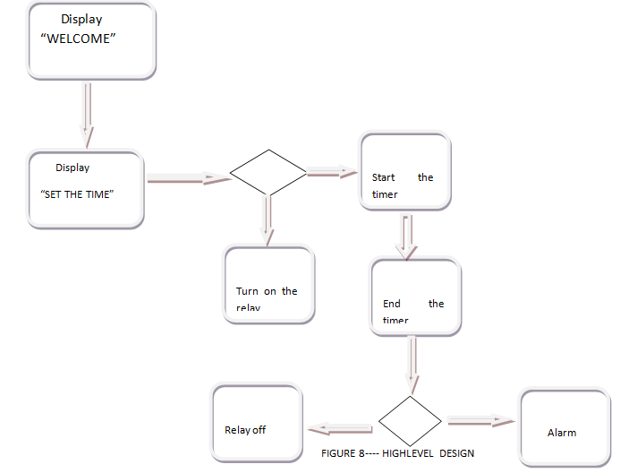
HIGH LEVEL DESIGN
Design and construction
Main circuit & final product
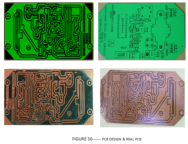
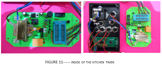
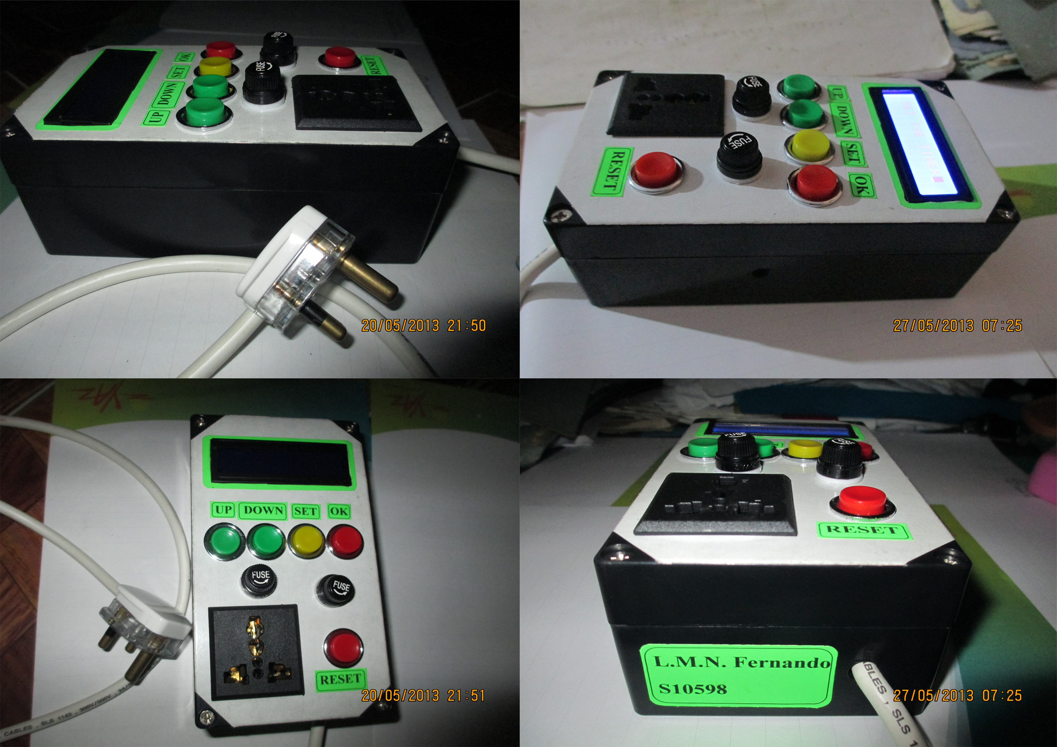
Figure 12—- final product
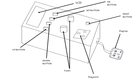
Figure 13— parts identification
Results
- When the kitchen timer device is powered on it will display “WELCOME” on the LCD display. It helps improve the user friendliness of the product
- After it displays the “WELCOME” on the LCD display it will automatically change to “SET THE TIMER” command after few seconds.
- Once it appears the “SET THE TIMER” command on the LCD display the user has to press the SET button to go in to the timer settings.
- Once the user presses the set button he first can change the hours by using the up button to increase and down button to decrease the value of hours. After set the number of hours of the timer user has to press the ok button.
- Then user can set the number of minutes that he wants by using the up button to increase and down button to decrease the value of minutes. After set the number of minutes of the timer user has to press the ok button.
- Since it is pressed the ok button after set the minutes the counter will start to down counter and automatically connect the external electrical equipment to the power up by using the relay.
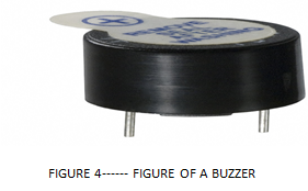
- Finally when the timer down counts and come to the end point or the timer value is zero the external electrical device will disconnect by using the relay and give an alarm signal to indicate the time is over to the user by using the Buzzer.
- Ultimately it will display “TIME IS OVER” on the LCD display.
Further improvements
- In this product I considered to control (connect and disconnect) one electrical device only at a time. But this device can be extended or modified to connect several numbers of electrical devices at same time and it may be useful to some cases.
- In my kitchen timer product user has to set the time at each and every time when he is going to start the timer (to connect the electrical device). But if this device has some memory storable capability. Then it can store some values what the user is frequently used. Then user doesn’t want to set the time each and every time when he is going to use this device.
- And also it can use a key pad, Instead of using push buttons to control the device. It will help to increase the easiness.
References
http://www.mikrocontroller.net/articles/AVR-Tutorial:_Timer
http://www.electroschematics.com/8512/microcontroller-relay-interface-and-driver/
http://electronics.stackexchange.com/questions/39503/is-this-a-proper-way-to-connect-a-piezo-speaker-to-mcu
Appendix A — schematic diagram
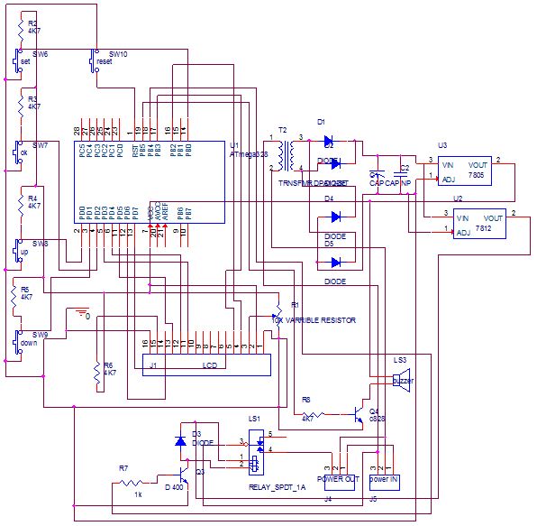
Figure 14— schematic diagram.
Appendix B — component list
| Component name | Quantity |
| 230v/12v(300MA) transformer | 1 |
| 7805 | 1 |
| 7812 | 1 |
| Pre assembled Bridge | 1 |
| 220UF (25v) | 1 |
| 100UF(16v) | 1 |
| 3 pin 5A socket | 1 |
Table 1 — component list of power supply circuit
| Component name | Quantity |
| 12V 5 pin relay | 1 |
| D400 transistor | 1 |
| 1K resistor | 2 |
| IN 4007 diode | 1 |
| LED | 1 |
| 10K resistor | 5 |
| 10K variable resistor | 1 |
| 33 ohms resistor | 1 |
| Micro switch | 1 |
| 5V Buzzer | 1 |
| C 828 transistor | 1 |
| 4.7 k resistor | 2 |
| 2 pin male connectors | 5 |
| 100 nf capacitor | 1 |
| 8 pin wire connector | 2 |
| 10 pin rebio1n wire connector | 1 |
| 16 pin male connectors | 1 |
| 28 pin micro controller base | 1 |
| LCD display | 1 |
| Push buttons | 5 |
| Fuse holders | 2 |
| 5A fuse | 2 |
| 3 pin universal socket | 1 |
| wire | 2m |
| 3 pin plug | 1 |
Table 1 — component list of main circuit