Contact Pubudu: pubuduaravinda90@gmail.com
Introduction
This project is base on mainly transport service section. In Sri Lanka there are many taxies. But there is no standard service charge for the journey. The service charge should base on length of journey and parking time. As solve of this I made the “taxi meter”. Through this service charge is count per kilometer and parking time with in the journey. It is online display to the customer and to the service supplier.
MATERIALS AND METHODS
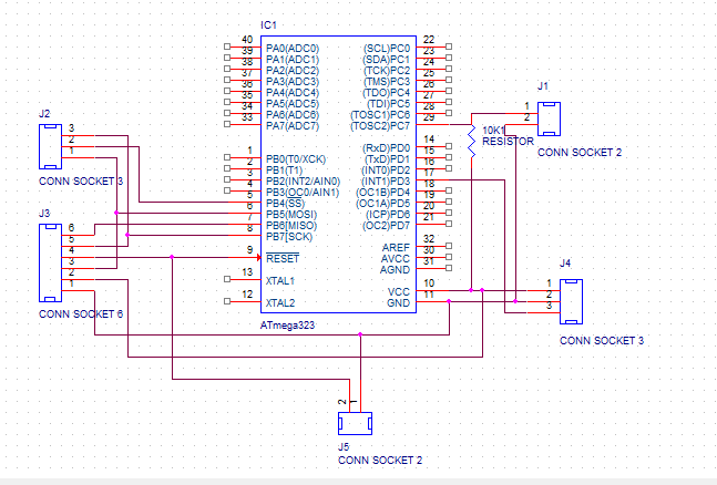
MICRO CONTROLLER
The micro controller is the heart of embedded system in taxi meter. It is taking rpm and doing calculations and transferring the massages into correct places.
For make the taxi meter I used Atmel 32A micro controller. It has 40 pins.

Max 7219 IC
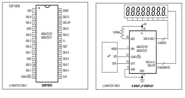
The MAX7219 is compact, serial input/out-put common-cathode display drivers that interface Microcontrollers to 7-segment numeric LED displays of up to 8 digits.
The devices include:
150µA low-power shutdown mode
Analog and digital brightness control
Scan-limit register that allows the user to display from 1 to 8 digits
Test mode that forces all LEDs on.
Operating Temperature Ranges (TMIN to TMAX): 0°C to +70°C
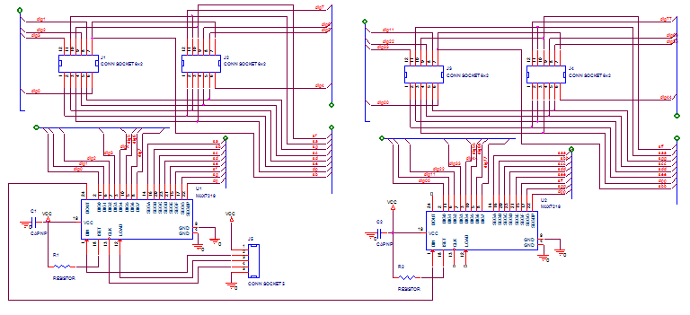
this can get SPI type data and can display that data through SSD. When we use tow max 7219s we should connect LOAD [CS] (pin no 12) and CLK (pin no 13) paralleled. For the data input of 2nd one, DOUT (pin no 24) of 1st max 7217 should connect to DIN (pin no 1) of 2nd max 7219.
There is no need to connect load resistance for SSD. Because this IC prepare for direct connect to the SSDs.
7segments

A seven-segment display (SSD) is a form of electronic display device for displaying decimal numerals that is an alternative to the more complex dot-matrix displays. Seven-segment displays are widely used in digital clocks, electronic meters, and other electronic devices for displaying numerical information.
The driver needs a few connections. First the power and ground are connected. Then there are 7 connections that need to be made from the driver to the LED display through a resistor. The resistor is just a current limiting component to keep from blowing the LED. MAX 7219 IC support to common cathode 7segments. there for we should use common cathode type 7segments not common anode once. When use common anode segment circuit diagram become to very complex. Should convert every LEDs in segment with changing their direction.
Infrared transmitter and receiver

I used infrared transmitter and receiver to capture the RPM of wheel. This is not very accurate sensor. There are many accuracy sensors in the market. When power supply to the emitter it emit the IR wave and receiver got it, it generate the voltage. Some obstacle cover the wave receiver will lose the power and fall down the voltage.

We should connect 150ohm resister (R1) to the emitter and 33 kilo ohm resister (R2) to the detector.
Voltage across IR emitter : 4.85 V
Voltage across detector (on output line) : Maximum voltage is less than 4.85 V
Minimum is zero
METHODS
The Algorithm that used to interface velocity, distance and service charge to the SSD from vehicle;
Using infrared or any type of detectors and capture the voltage varying Patten.
Check that voltage varying sufficient or if it is happen for per circled.
Voltage varying give to the microcontroller as input interrupt and used INT1 interrupt pin. (in my microcontroller, it is PORTD3)
Using the count of wheel and radius of wheel calculate the distance and service charge. (When we use different type of vehicle we should get average standard radius.)
Using the timer counter internal interrupt per second and take round of wheel per second.
Using round per second and radius of wheel of vehicle calculate the velocity of vehicle.
Price, distance, speed those values send in to max7219 IC and display those in seven segments.
Set tow button one is start the hire and other is stop the hire.
Eexternal Interrupts
In the atmega32A has the External Interrupts that are triggered by the INT0, INT1, and INT2 pins. Observe that, if enabled, the interrupts will trigger even if the INT0:2 pins are configured as outputs. This feature provides a way of generating a software interrupt. The external interrupts can be triggered by a falling or rising edge or a low level (INT2 is only an edge triggered interrupt).
This is set up as indicated in the specification for the MCU Control Register – MCUCR – and MCU Control and Status Register– MCUCSR. When the external interrupt is enabled and is configured as level triggered (only INT0/INT1), the interrupt will trigger as long as the pin is held low.
Note that if a level triggered interrupt is used for wake-up from Power-down mode, the changed level must be held for some time to wake up the MCU. This makes the MCU less sensitive to noise. The changed level is sampled twice by the Watchdog Oscillator clock. The period of the Watchdog Oscillator is 1 μs (nominal) at 5.0V and 25°C.
Internal interrupt
The Timer/Counter can be clocked by an internal or an external clock source. The clock source is selected by the Clock Select logic which is controlled by the Clock Select (CS12:0) bits located in the Timer/Counter Control Register B (TCCR1B).
SPI data transferring to the MAX 7219
Using one MAX7219 can light eight digit numbers. There is SPI data register in our microcontroller. It is 16 bit data register. We have to enable this register of micro controller.
MAX 7219 need clock signal line, load line and data input line from micro controller. We have to assign corresponding pins on micro controller. In Atmega 32A PORTB4 is load, PORTB5 is MOSI (data input) and PORTB7 is clock signal line.
When we use tow MAX7219 ICs data input of 2nd IC is the data output of 1st IC. SCK and LOAD is the same line. After the 16.5 clock cycle data enter to the 2nd IC. As an idea the clock signal help to assign each data in to each register, data send by serially. Then clock count the count and select correct data into correct bit. Duty of load and SS are like, give massage to screen loaded data in register. When SS in logic zero it take data again
CONSTRUCT THE MOTHER BOARD
I made mother board with tow main part. one is micro controller included part other is MAX7219 with SASDs
microcontroler


MAX7219 with SSDs


.
Mother board component list
| Component | Quantity |
| Atmeg 32A | 1 |
| 40 pin IC base | 1 |
| Max 7219 IC | 2 |
| 0.1µF capacitors | 2 |
| 6 way wire connector | 1 |
| 3 way wire connector | 2 |
| 10 k Ω resistor | 2 |
| 2 way wire connector | 2 |
| 7 segments(four times sets) | 4 |
Software
I used WINAVR to write sourse code to take count through the interrupt.
after the calculation send the values to MAX 7219 and display through it
VOLTAGE AND CURRENT LIMITATION
For microcontroller:
Operating Voltages of MC: 2.7V – 5.5V
Power Consumption (at 1MHz, 3V, 25°C) of MC: – Active: 0.6mA
– Idle Mode: 0.2mA
– Power-down Mode: < 1μA
For MAX7219:
Voltage (with respect to GND)
V+: -0.3V to 6V
DIN, CLK, LOAD, CS: -0.3V to 6V
All Other Pins: -0.3V to (V+ + 0.3V)
Current
DIG 0–DIG 7 Sink Current: 500mA
SEG A–G, DP Source Current: 100mA
PROBLEMS FACED AND THE REMEDIAL MEASURES
There is lot of problems I had to face with this project. I started this with characteristic of IR sensor. I set IR emitter and detector in to active mode. Then I had screen when we break the beam detector voltage going down. Then it set to the microcontroller as switch. When we break the beam I got count and display it through SSD. But that count appears to only slow motion, when I did fast count it didn’t get as normal switch count.
Then I had taken external interrupt. I did past case with interrupt I got real count. Then made the test wheel and made hole in wheel and got result through it. Then on the timer counter interrupt and took the RPM also.0
Result checked with stroboscope, and there is small error with real RPM and given RPM. Reason is delay of IR sensor. The IR sensor work correctly within 0 to 9 rounds per seconds. When it goes up it is giving small error. As a solution of this there is only one error and only one solution, that is we have to use RPM detector sensors that made for count the RPM of vehicles.
Finally I got result individual. But cannot display all result using microcontroller. Because pot put pins are not sufficient for needed SSDs. Then I had to use max 7219 IC. I gave my result to the max 7219 and it connects to the SSDs. Through that I displayed the all results. There are many problems in max 7219 IC and I had to spend more time with it.
ANALYSIS
Accuracy of every value is very important spicily distance and price. Because this equipment handle some exchange of money. In microcontroller external interrupt pin has the five microsecond delay. It is very small. The time of count after next count is always lager than it. Because practically RPM of vehicle wheel cannot be like that value.
The range of microcontroller is in our optimise range. But signal transfer wire can take some time. And that signal voltage should between 0V-5V ranges.
In this case I used two type detectors. One is normal infrared emitter and detector. In there I made hole in wheel and it pass the sensor detector’s voltage goes up and again it goes down, because whole is close. When RPM increase detector voltage can on going down and quickly whole can set. As this scenario detector can avoid the signal. It depends on delay time of detector.
For the solution of this we can decrees the intensity of emitter by varying load resister. Then detector get low signal and it goes down quickly.
I checked real RPM and taxi meter’s RPM by stroboscope. The used motor gave the around 10 rounds per second and SSD showed 8-9 rounds per second. When I used colure detector sensor I got 9-10 rounds per second.
We can used high accuracy level sensor those specify for calculate vehicles RPM correctly and voltage limit of those should in 0V-5V.
IMPROVEMENTS, FURTHER WORK OR RECOMMENDATIONS
This product can use for any kind of vehicle and can change the rate according to standard of service. We just need radius of wheel.
APPENDIX 1:Schematic diagrams