Introduction
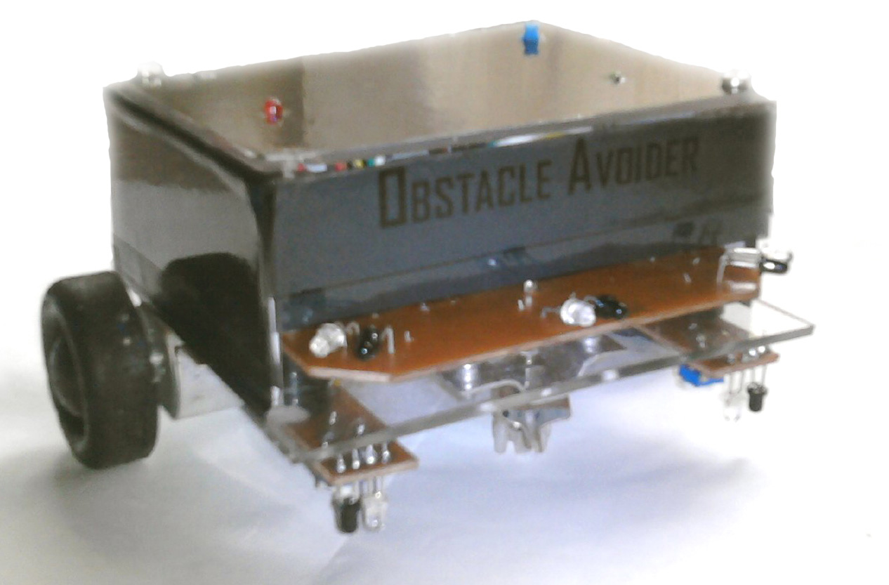
Obstacle Avoider is a simple robot car that is moving an area by avoiding obstacles on its path. While it is moving forward it checks whether there is an obstacle on its path by using optical sensors on it and when it recognized an obstacle on its path, it is starting to turn left or right until the path is clear. When the path is clear, it is again moving forward. Also it has sensors on bottom side to protect falling down from stairs.
Materials and Methods
ATmega328
The AVR microcontroller ATmega328P is used for this device. The Analog to Digital Converter (ADC) of the MCU is used to read output voltages of the sensors. ATmega328p has 6 multiplexed single ended input channels for ADC. The Pulse Width Modulation (PWM) of MCU is used to control the speed of the motors. There are 6 PWM outputs on ATmega328.
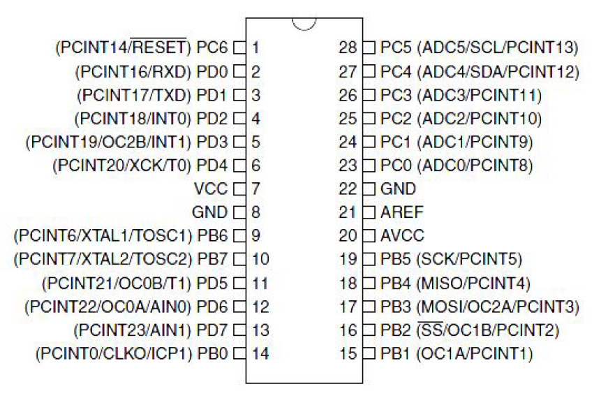
Figure 1: Pin diagram of the ATmega328 PDIP package
IR Transmitter and Receiver LED pair
There are more accurate sensors like ultrasonic range finder, sharp IR range finder etc. are available in the market to detect obstacles. But they are more expensive. Therefore I used IR Tx and Rx LED pairs which is cheap and good for my device. I mounted these sensor pairs that the IR rays transmitted by the IR Tx are incident on surfaces and reflected IR rays are incident on IR Tx.
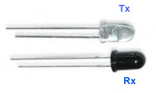
Figure 2: Physical view of IR Tx and Rx
L298 Motor Driver IC
The differential drive system is used to control the moving directions of the device. Therefore it can be moving forward, reverse and turn left or right by using only 2 motors. The H Bridge can be used to drive a motor bidirectional ways. The L298 motor driver consists with 2 H-bridges and can be driven maximum output current up to 2A.

Figure 3: Pin diagram of the L298
High Level Design
The resistance of the IR receiver LED is decreasing when IR rays are incident on it. These IR Rx are respond only for the IR rays. This phenomenon is used to detect obstacles. Since resistance of the Rx is varying with amount of IR rays incident on it, different output voltages can be obtained when obstacles are near and far. It can be convert these analog voltage levels to digital by the MCU.The 4 inputs of the L298 motor driver are controlled by the MCU to turn left or right and moving forward or reverse.
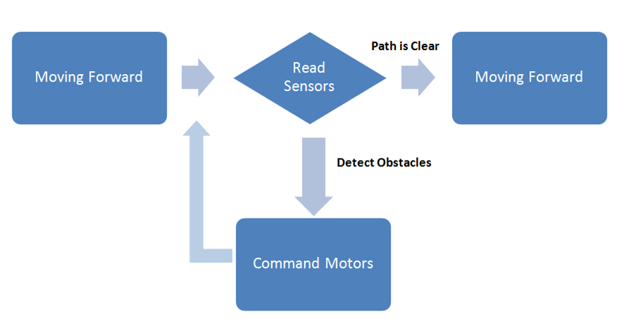
Figure 4: High Level Design diagram
Hardware
I designed the mother board small much as possible to reduce the size of the device. I designed 3 sensor boards separately and connected with the mother board by using connector sockets.OrCAD 16.5 is used to design the PCB layouts. In the mother board there are two power supplies separately for motors and the main circuit. There is a jumper if someone wants to power by only one source.There is a 10 pin header box on it to directly connect the FRC cable of the usbasp programmer. Two motors and the circuit boards are mounted to a Perspex board using nuts. Therefore it can be easily unmounted all the components.Two wheels are collected from a toy cart and a caster wheel is made myself by using railings and nuts.
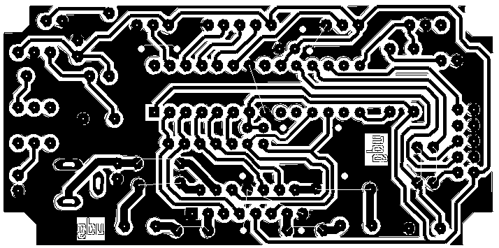
Figure 5: Mother board PCB layout
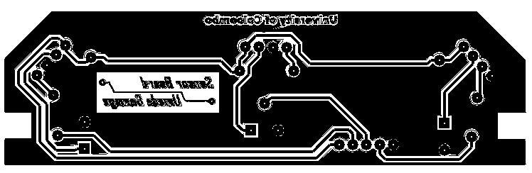
Figure 6: Main sensor board PCB layout
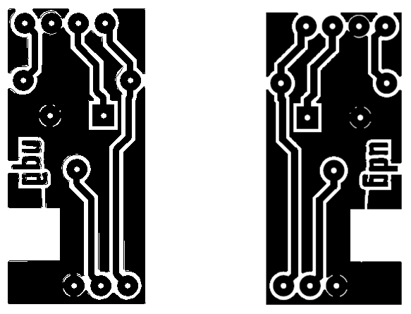
Figure 7: Down sensor boards PCB layout
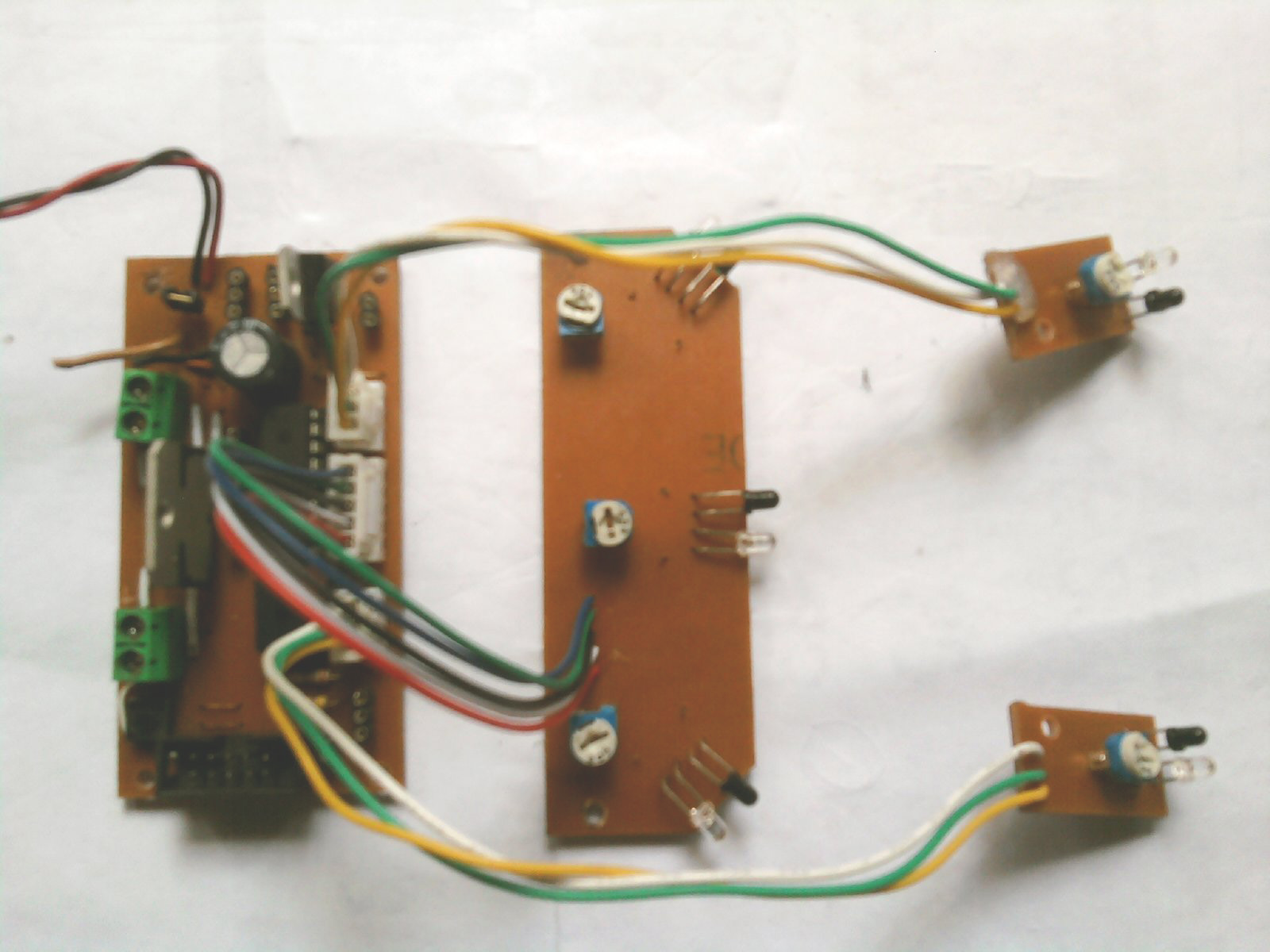
Figure 8: PCB circuits
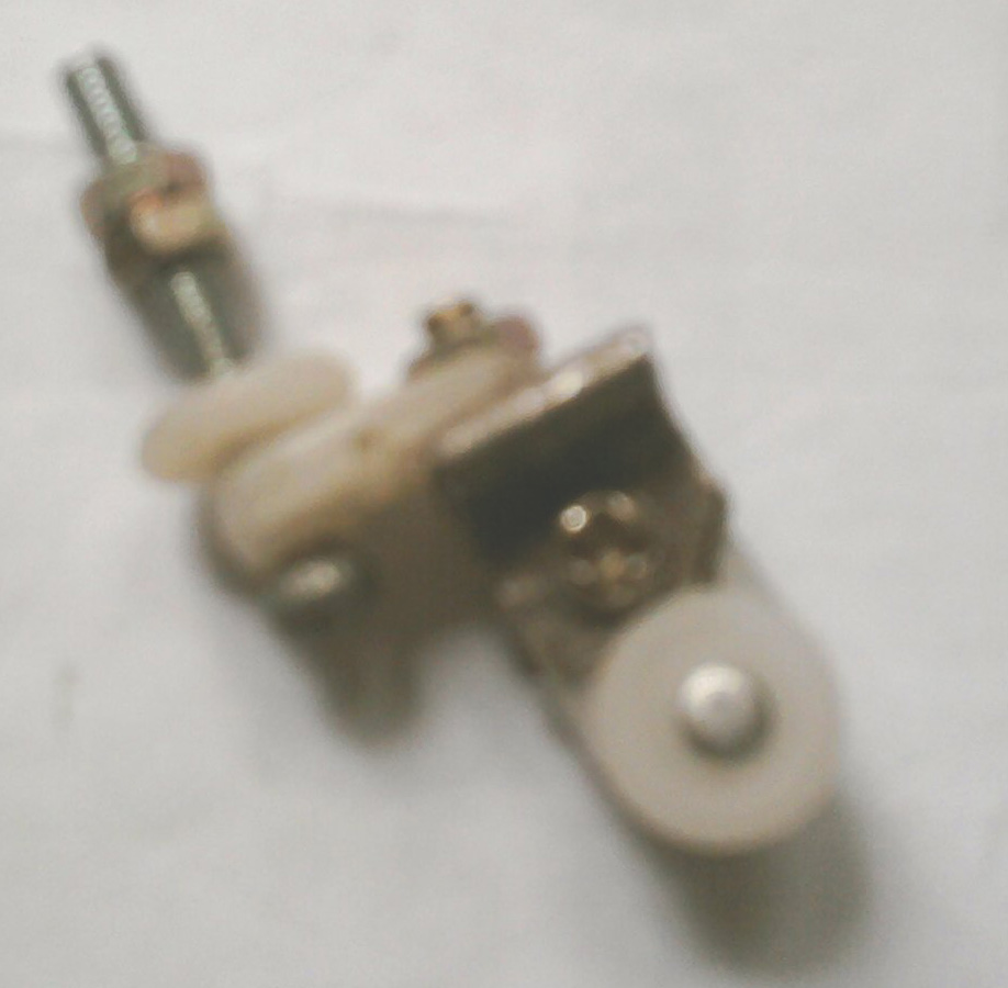
Figure 9: Caster wheel
Software
The WinAVR is used to writing the source code, compilation and download to the MCU. Five ADC values of the five sensors are compared with the fixed values defined for each sensor. The logic inputs of the motor driver are providing to rotate motors clock wise or counter clock wise.
Results
The device detects obstacles and turn left or right. It moves very fast. Therefore the down sides sensors are don’t response before falling down the device. The sensitivity of the IR receiver is different to obstacles with different surfaces. This is due to the reflection of the IR rays on a surface is dependent on the colour of the surface, material etc. The black surfaces are most absorb IR rays and the white surfaces are most reflect IR rays.
Further Enhancements
It is better to use gear motors to drive the device with more load. And also it is better to use a caster wheel made for standard specifications. The power supply for the motors can be providing by using batteries having large capacities. It is recommended to use a 6 pack of rechargeable AA battery. It can be drive on rough surfaces by replacing the caster wheel by two other wheels.
Bibliography
1. L298 Datasheet. (2000). Retrieved from Sparkfun: https://www.sparkfun.com/datasheets/Robotics/L298_H_Bridge.pdf
2. Atmega328 datasheet. (2012). Retrieved from Atmel: http://www.atmel.com/products/microcontrollers/avr/default.aspx?tab=documents
3. IR sensor LED. (n.d.). Retrieved from Engineers Garage: http://www.engineersgarage.com/articles/infrared-sensors
4. Mayank. (2011). AVR Timers – PWM Mode. Retrieved from MaxEmbedded: http://maxembedded.com/2011/08/07/avr-timers-pwm-mode-part-i/
5. Weerasingha, P. (2011). Line Following Car. Retrieved from Embedded System Laboratory Project Page: University of Colombo: https://sites.google.com/a/sci.cmb.ac.lk/esl/mini-projects/2011/line-following-car
Appendix A: Hardware Schematics

Figure 10: Mother Board schematic
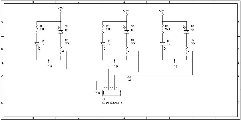
Figure 11:Daughter Card schematic
Appendix B: Component List
| Component | Quantity | Cost(Rs) |
| IR LED | 10 |
100.00 |
| ATmega328 | 1 |
500.00 |
| 28 pin IC base | 1 |
12.00 |
| L298 | 1 |
240.00 |
| On/Off switch | 1 |
12.00 |
| 9V batry connector | 1 |
20.00 |
| 9V dc motors | 2 |
170.00 |
| 9V Battery | 1 |
50.00 |
| DC shocket | 1 |
5.00 |
| 50k Preset | 5 |
25.00 |
| 2 way switch | 1 |
10.00 |
| 5 pin wire connector | 1 |
17.50 |
| 3 pin wire connector | 2 |
24.00 |
| 150 Ohm resistor | 5 |
2.50 |
| .1uf capacitor | 3 |
3.00 |
| 2 pin terminal | 2 |
30.00 |
| 10 pin header box | 1 |
10.00 |
| 3mm LED | 2 |
2.40 |
| Total Cost (Rs) |
1,233.40 |
|