Introduction
over view
We have main three colors (Red, Blue & Green) which can produce a broad array of colors. They called as RGB colors. When mixing two or more of these primary colors, we can produce any colored:-red+green=yellow, blue+red=puple.RGB output devices are TV set of various technologies (CRT, LCD, PLASMA), Computer, mobile phone display and video projectors, etc.

FIGURE 1-RGB COLOR
Light,an electromagnetic wave,can come in different wavelength.this wave enters our eyes and energy of the wave convert into chemical energy.by this energy our brain identify.if wave length and corresponding color.this the way that our eyes identify colors.so the every color has fixed wave lengths and there are between the visible range of electromagnetic spectrum.

FIGURE 2-2 ELECTROMAGNETIC SPECTRUM
So actually any color is the range of wave length which are in visible range of spectrum. When we look a green paper, the paper isn’t actually green.instead,the molecular surface on the paper reflects wave lengths that appear green in our brain and absorb the other wave lengths molecularity .
When we shine a blue led on both blue and red papers, the blue paper reflect more light than the red paper because the blue paper is not absorb energy from the blue light, but red paper is absorb energy from the blue light. So it not reflects the blue light. If we shine a red led, red paper reflect more light than the blue paper.

FIGURE 3-COLOR REFLECTING
In my project also use this theory to detect the colors, I used RGB led and one LDR.when shine the RGB light on the object if reflect the more light which is corresponding to the object color.
material and methods
Here I use the two RGB Led with one LDR.when the push button is press,RGB will turn on .first the blue light and hold it for 200ms.then LDR reading it’s voltage(analog voltage) and send to ADC pin.(ADC4).this value is sent to the EEPROM.then turn on the green light and do the same procedural. Then the red one.
Here we can see that when object color same as the LED color ADC gives higher value than the other two values. This method is use in my project to detect the color.

FIGURE 4-LDR CIRCUIT
Pulse width modulation
Here I used PWM for changing the brightness of each LED. because red & green colors are more brighter than the blue light. So it a more effect to final result. To avoid of this problem, reduce the brightness by using pulse width modulation.
Our micro controller has 6 pin which can use for PWM
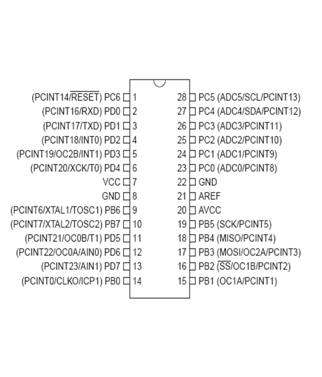
FIGURE 5-ATMEGA328 MICRO-CONTROLLER
Analog to Digital Conversion
Analogue to digital conversion is the process representing the analogue signal as a series of number. So here LDR gives the analog value when the light is flashing.but we want to get digital values of corresponding to these analog values. So we should use the ADC .our micro-controller has 6channel for ADC.but here I used only one channel,ADC4. This analog to Digital converter has 10bit resolution. Therefore its maximum value is (2^10)-1 that is 1023. Then register value correspond to our reference voltage is lie between 0 and 1024.

FIGURE 6-1 ADC PINS
eeprom data memory
The AVR architecture has two main memory spaces, the Data Memory and the Program Memory space.In addition, the ATmega48P/88P/168P/328P features an EEPROM Memory for data storage. In this project ,I used EEPROM to save the adc value of Each steps. one location can save 0 to 255 value
Ex:- EEPROM_write(0x02, c)
EEPROM_write(0x03, d);
Values can read by
val_2 = ((EEPROM_read(0x03))+EEPROM_read(0x02));
design and construction
design
To design my main pcb,I used cadence 16.6 software. One pcb done with express pcb.first I was drawn the schematic of LED circuit. Because it was the main thing in my project. Because I want to focus the light beam to one point and LDR must place in middle of both RGB Led. But this pcb done with express pcb software.

FIGURE 7-1 PCB LAYOUT 1
| COMPONENTS | DESCRIPTION | QUANTITY |
| resister | 570ohm | 1 |
| Variable resister | 10k ohm | 3 |
| Male connector | 40 pin | 1 |
| Push button | – | 1 |
| Ic Base | 28pin | 1 |
| micro controller | At mega 328 | 1 |
| connector wire | Female to female | 20 |
Table ‑1.component table for LDR circuit
Then I drew the main circuit with cadence 16.6 software. Here I used the one resister, 3 variable resisters, push button, one LCD display and atmega328 micro-controller. To connect push button, LED circuit and LCD display, I used male to male connect wires.

FIGURE 8-SCHEMATIC OF MAIN CIRCUIT

FIGURE 9-MAIN CIRCUIT PCB
| COMPONENT | DESCRIPTION | QUANTITY |
| RGB LED | 5mm | 2 |
| LDR | — | 1 |
| Connector | 1pin | 1 |
| Connector | 2pin | 1 |
Table -2.component table for main circuit
POWER SUPPLY
In my device, I used 12-5v dc supply as power supply.used components are
Table -3 component table for power supply circuit
| COMPONENTS | DESCRIPTION | QUANTITY |
| Male connector | 40 pin | 1 |
| capacitor |
0.1u |
1 |
| capacitor | 0.33u | 1 |
| regulator | LM7805 | 1 |
| Diode | IN4007 | 1 |

FIGURE 10-SCHEMETIC OT POWER SUPPLY CIRCUIT
construction


FIGURE 11 PICTURE OF MAIN CIRCUIT
RESULT AND ANALYSIS
- Here I used the LCD display to display the color name.
- Product having two buttons only, so it’s friendly to users.
- This device can detect four colors.
- Can program this device in any anytime, with easily.
- This device can working with 5-12 dc voltage supply.