INTRODUCTION
Overview
Time is most important thing of our life. Everything is change with time. Nobody can stop or chapter it. We do something in our day to day life at time. The whole world created a method for represent time. We use watch to known the time. There are several types of watches. Watches, Clocks…etc. The first watches are generated by mechanical system. After lot of things are change when the transistor found. Electronic science develops rapidly. Then most mechanical system converts to electronic system. So now days most watches are also create by electronic system. They are cheaper than old mechanical system watches. The lot of information like day, month…are represent in small display in the electronic watches. And most features are including it. Timer, Alarm and Other functions are available in electronic watches.
This Project is also LCD electronic watch. Year, Month, Date, Day and Time Display. It can set on time and can set the alarm. The LCD Display has Yellow Black Light. Therefor time can see at the night time too.
Materials and Method
Mainly here use three components. Those are AVR Microcontroller, RTC Module and LCD Display. RTC Module use for real time. It has several data. Year, Month, Day and Time with Hour, Minute, Second. These values get to the main file and display its using LCD.
The Method of LCD Display and RTC module include the separate header files. Therefore these files need to include the main.c file.
The WinAVR is importance software of this project. All c Codes are made by using Programmers Notepad [WinAVR].
Hardware components
Atmega328 AVR Microcontroller
AVR Microcontroller IC is main part of in this project. Here use 28 pins AVR Microcontroller. The 23 pins are I/O pins. ATmega328 is support up to 20MHz speed. It contains two 8bit and one 16bit Timer/Counter. There is external interrupts to capture an external event like pressing a push button. It has an Electrically Erasable Programmable Read Only Memory (EEPROM) which is nonvolatile. It can be used for storing data permanently on chip.TheTmega328 has 256 Bytes EEPROM and has an endurance of at least 100000write/erase cycles.
The pin diagram of AVR Microcontroller given bellow in Figure 1.
Figure 2‑1 pin diagram of the Atmega 328p
16×2 LCD Display
It contains 16 columns and 2 rows. Each character represented by a 5×7 matrix. It should be adjust the contrast by using a variable resister until display the characters clearly. Here LCD module used in 4-bit mode.
Figure 2‑2 LCD Display
Push Buttons
If the push button is pressed the two terminal of the button are connected until the button is released. If the push button is pressed 0V is applied to the port of the Microcontroller. When it is released 5V applied to the port.
Figure 2‑3 Push button
Resistors
A variable resister is used to adjust the contrast of the LCD.
RTC
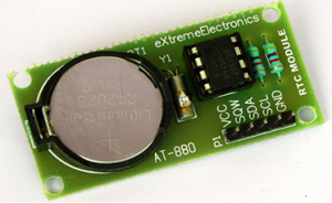
An RTC Module or a Real Time Clock Module helps a system keep track of current time. It is automatically increments the time without any help from the microcontroller. Other benefit is that it has a backup power supply from a small coin cell that help it maintain the time in absence of power.RTC IC is DS1307. It communicates with the microcontroller using 12C serial interface.
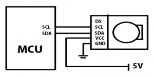
The SCL line of RTC Module will be connected to SCL line of MCU similarly the SDA line will be connected to the MCU’s SDA line.
Figure 2‑4 RTC module
Figure 2‑5 RTC module connection to MCU
Buzzer
A buzzer is an audio signaling device, which may be mechanical, electromechanical or Piezoelectric. A buzzer or beeper is a signalling device, usually electronic, typically used in automobiles, household appliances such as a microwave oven, or game shows. It most commonly consists of a number of switches or sensors connected to a control unit that determines if and which button was pushed or a preset time has lapsed, and usually illuminates a light on the appropriate button or control panel, and sounds a warning in the form of a continuous or intermittent buzzing or beeping sound. Initially this device was based on an electromechanical system which was identical to an electric bell without the metal gong.
Figure 2‑6 Buzzer
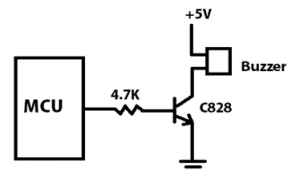
Buzzer has two terminals like Positive and Negative. The Positive pin connected to the +5V and other terminal connected to the Collector of the transistor.
Figure 2‑7 buzzer connect to MCU
Here used C828 Transistor for connected to the Buzzer. The transistor acts as switch mode.
Method
The Algorithm used to Interface RTC Module to LCD Display.
- RTC module used to get Real time data.
- This RTC values get to variables and arrays.
- Pass the Output to LCD.
- Four Buttons used for change to data.
- The Interrupt used only for one Button which is Settings Button.
- Other three buttons are used for UP, DOWN and SET.
The AVR architecture has two main memory spaces, the Data Memory and the Program Memory space. In addition, the ATmega48P/88P/168P/328P features an EEPROM Memory for data storage. The Alarm is main function in this Project. Here used EEPROM for store the alarm data. Therefore Alarm data is not erase when the power off or battery charge goes to down. EEPROM has 10bit Address register. These each address has 8bit memory capacitor. Alarm can set any time in any day. Therefore six types of data value need to store in memory. Six data Address used for it.
High Level Design
The Watch has four Push buttons. The One is Interrupt button. It is use for Options. Firstly it displays “WELCOME”. Then run the Time. It can going to Options and can it change using Push buttons.
Low Level Design
Firstly display “WELCOME” command. After few seconds it is display Year, Month, Date and Day in upper row. The time and alarm sign display in bellow row. It can change or set any details by click the “Settings” push button. There are two Options “Settings” and “Alarm” display after clicked the settings push button. One Option can choose using “Up” or “Down” push button. It is going to Settings if click the Up Push button. Also it is going to Alarm if click the Down push button. Then Settings and Alarm can set using Push buttons. Alarm can set for any day and any time.
Design and Construction
Firstly checked the circuit components are connecting on the bread board. The schematic diagram drew using OrCAD capture CIS after checked the circuit. The PCB layout is design using PCB Editor. Then PCB layout got to the copper board. All hardware components checked and attached to the PCB. The casing designed after checked final circuit.
It has two types of Power Supply system. One is temporary system. That is from USB connection. If USBASP connect to watch then other supply is not working. Other power supply is coming from external Battery. It is a 9V battery. But this 9V cannot give to microcontroller directly because its maximum voltage value is 5.5V. 7805 regular IC uses for convert to 5V from 9V. A diode uses for no current flow from battery when the USBASP connect.
Table 3‑1 Regular circuit
Mother Board
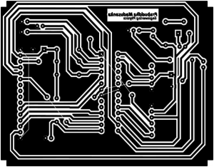
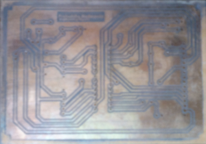
This is only PCB board of This LCD watch Project.
Figure 3‑1 PCB Layout
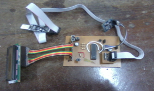
Figure 3‑2 PCB Layout
Table 3‑2 Circuit with components
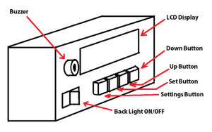
Figure 3‑3 cassing diagram
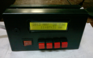
Figure 3‑4 final product
Components
Table 3‑3table of components
Voltage and Current Limitation
9V DC Voltage supplies to the Mother Board from Battery. This voltage convert to 5V using 7805 regulator IC. This 5V provide to Hardware components.
AVR Microcontroller
Minimum Voltage is 4.5V and Maximum Voltage is 5.5V
Maximum Current is 40mA
RTC Module
Minimum Voltage is 4.5V and Maximum Voltage is 5.5V
Result and Analysis
The all hardware components checked one by one. Those worked well. Therefor all components attach to the Mother Board. Firstly LCD display was not displayed anything. Then it could found some PORT error in header file when the checked the Header file of the LCD Display. So checked again after solve the problem. The all input values of RTC Module are Digital. It had to use if condition for digital values converted to names of Years, Months and Week days.
Discussions and Conclusion
The Method of LCD Display and RTC Module are including in Library files. These files are known as ‘Header’ files. A main problem was how to find suitable header file. The RTC header file included to the folder which contain main.c file, but RTC was not worked after compile. So it had to some change in header file. Then it is worked.
Bibliography
Atmel Datasheet : ATmega48A; ATmega48PA; ATmega88A; ATmega88PA; ATmega168A; ATmega168PA; ATmega328; ATmega328P. Online available at www.atmel.com/images/atmel-8271-8-bit-avr-microcontroller-atmega48a-48pa-88a-88pa-168a-168pa-328-328p_datasheet.pdf
Interrupts 65p
External interrupts 19p – 25p
EEPROM 71p – 73p
Extreme Electronics AVR Tutorials: Using LCD module with AVR. Online available at http://extremeelectronics.co.in/avr-tutorials/using-lcd-module-with-avrs/
Extreme Electronics AVR Tutorials:DS1307 Based RTC Module. Online available at
http://extremeelectronics.co.in/electronics/ds1307-based-rtc-module/
Appendix
Schematic diagram
Figure 6‑1 Schematic diagram
Code
The main.c ,RTC.h and the lcd.h files can be find in the attachment.


